
 WhatsApp: +86 16626708626
 Email:
  Phone: +86 16626708626
Description
Key Technical Specifications
- Manufacturer: Applied Materials, Inc. (AMAT)
- Part Number: 0100-71443
- Product Family: AMAT AKT semiconductor/display-manufacturing equipment
- Published Board Description: Chamber Distribution 55K CVD Board
- Primary Use: Internal chamber distribution, control, or interface function within compatible AMAT AKT CVD equipment
- Equipment Category: Semiconductor and advanced-display manufacturing equipment
- Form Factor: OEM printed circuit board assembly
- Host Architecture: Public reseller sources also describe a VMEbus interface role; verify against the installed machine documentation
- Physical Compatibility Requirement: Match part number, board revision, PCB layout, connector count, keying, mounting points, and installed location
- Electrical Ratings: Supply voltage, current draw, channel assignments, and connector pinout are not publicly verified
- Firmware/Configuration: Publicly unverified; document labels, jumpers, host diagnostics, and configuration before replacement
- Replacement Requirement: Use the exact 0100-71443 board unless Applied Materials provides a documented supersession
Public listings identify AMAT 0100-71443 as an AKT chamber distribution “55K CVD board.” Other reseller listings describe it as a VMEbus interface card or a generic semiconductor controller. Those descriptions are not fully consistent, so the chamber-distribution identification is useful for search and sourcing, but the machine schematic and original-board markings must control the final compatibility decision.
Product Introduction
The Applied Materials 0100-71443 is an OEM board associated with AMAT AKT chamber hardware for semiconductor or advanced-display CVD equipment. A semiconductor-spares catalog identifies the assembly as a “chamber distribution 55K CVD board,” indicating an equipment-specific internal distribution or interface role rather than a general-purpose PLC card.
This is an exact-replacement spare for a legacy AMAT tool. Match the complete 0100-71443 number, board revision, connector arrangement, mounting pattern, installed slot or enclosure location, and machine wiring documentation before ordering. Do not substitute a visually similar AMAT board or rely solely on generic “VMEbus interface” descriptions.
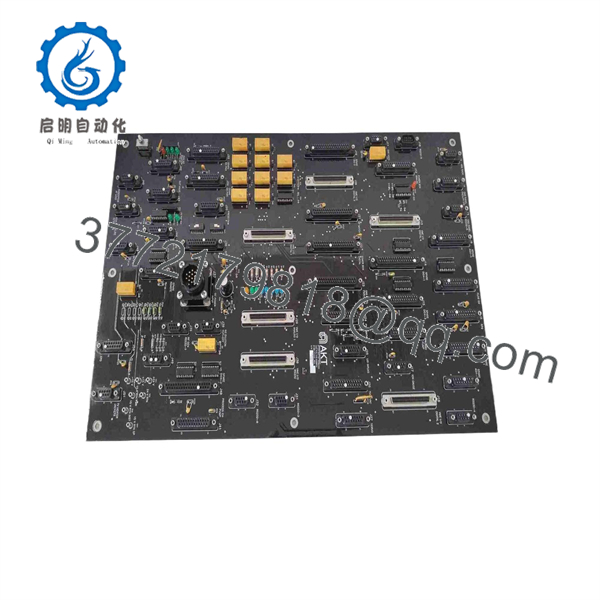
0100-71443
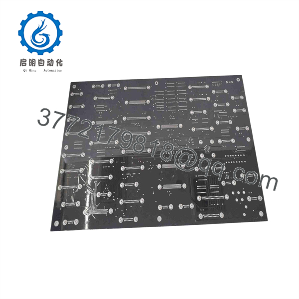
0100-71443
Troubleshooting Quick Reference
| Symptom | Possible Cause | Relevance to This Part | Quick Check Method | Recommendation |
|---|---|---|---|---|
| Chamber subsystem will not initialize | Missing DC supply rail, upstream fuse failure, interlock open, connector not seated, host-controller issue, or failed board | ✅ High | Follow the equipment lockout/tagout procedure. Read the exact tool alarm. Check the schematic for the board’s assigned power rails, then measure those rails at the board connector using a Fluke 115 or equivalent meter. Check applicable upstream fuses and power-supply status. | Verify all upstream power and interlocks before replacing the board. A no-start fault often originates outside the PCB. |
| Chamber distribution or CVD subsystem alarm occurs at startup | Board failure, wrong board revision, incorrect connector placement, damaged header pin, or configuration mismatch | ✅ High | Photograph the installed board, labels, connectors, and harness routing. Compare the installed card with the replacement part number and revision. Inspect mating connectors for bent, recessed, or oxidized pins. | Use only an exact 0100-71443 replacement unless AMAT documents an approved substitute. |
| One chamber-related device or branch remains inactive | Failed field device, open cable, local fuse, interposing relay, external power issue, or one failed board circuit | ✅ Medium | Use the OEM electrical drawing to trace the affected branch. Measure the source signal or supply at the field device and again at the board-side connector. Check fuses, terminal blocks, and continuity with power removed. | Isolate the external branch first. Do not replace a rare board solely because one actuator or sensor has failed. |
| Several faults appear after maintenance | Harness connected to the wrong header, loose connector, disconnected shield, disturbed grounding, or incomplete reassembly | ✅ Medium | Compare current cable routing against pre-maintenance photographs and labels. Verify connector keying, retention clips, shield termination, and cabinet ground connections. | Recheck every connection before powering up again. Similar connectors can be close together on legacy equipment. |
| Host controller reports interface or communication timeout | Host controller fault, board not seated, interface connector damage, wrong hardware revision, or incompatible host configuration | ✅ Medium to High | Review the controller diagnostic log. Reseat the board with power removed. Inspect the card edge, backplane, and connectors. Compare all original board markings with the replacement. | Confirm host-system compatibility from the AMAT tool documentation. Do not assume VMEbus functionality applies to every 0100-71443 installation. |
| Tool faults only after warm-up or long production run | Thermal stress, marginal power supply, cracked solder joint, intermittent connector contact, or external load changing with temperature | ✅ Medium | Review logs for time-to-fault. With approved safety controls, inspect connector retention and cabinet cooling. Measure relevant supply rails during the fault if the procedure permits. | Correct cooling and power issues first. If a controlled substitution with a verified matching board removes the fault, retain test evidence. |
| Burn mark, odor, discoloration, or visibly damaged component | Overvoltage, shorted downstream load, failed power component, liquid contamination, or internal board failure | ✅ High | Do not apply power again. Photograph both board surfaces. Check the relevant external circuit for shorts to ground or between supply rails before installing a replacement. | Find and correct the root cause before installing another 0100-71443 board. A replacement can fail immediately if the downstream fault remains. |
| All chamber functions remain normal, but a single process alarm appears | Process recipe issue, gas delivery issue, vacuum issue, RF subsystem fault, sensor drift, or another chamber subsystem | ❌ Low | Review the alarm hierarchy and process trend data. Check the first initiating alarm instead of the final cascade alarm. Verify the affected subsystem according to the tool’s maintenance procedure. | Do not replace the board without direct evidence. Process alarms frequently originate outside the control-card assembly. |
❗ Revision warning: Record every marking on the removed board before it leaves the machine. A technician can install a board with the same base number but a different revision or connector arrangement and create faults that look like an equipment failure.
❗ Harness warning: Take photographs before disconnecting anything. This is not optional on legacy chamber equipment. One misplaced connector or lost shield ground can create an interlock or communication fault that burns hours of troubleshooting time.
❗ ESD warning: Use a grounded wrist strap, handle the PCB only by its edges, and place it in an ESD shielding bag immediately after removal. I have watched a technician handle a high-value board without ESD protection during dry weather; it powered up once, then failed during the next production run. Use the wrist strap.
If the diagnosis remains uncertain, provide technical support with the AMAT tool model, chamber type, complete alarm text, diagnostic logs, clear photos of both board sides, connector labels, and all part/revision markings. Keep these checks in mind and you will save yourself 90% of typical rework time.
Frequently Asked Questions (FAQ)
What is AMAT 0100-71443 used for?
AMAT 0100-71443 is an Applied Materials AKT equipment board associated with chamber distribution in a 55K CVD application, according to a semiconductor-spares catalog. It is an equipment-specific assembly used inside AMAT semiconductor or advanced-display manufacturing hardware, not a generic industrial automation module.
Is 0100-71443 definitely a VMEbus interface card?
Not necessarily. One reseller calls it an AKT VMEbus interface card, but another describes the same part number as a chamber distribution 55K CVD board. This conflict matters. Do not order based on the VMEbus label alone; verify the original board, connector arrangement, installed location, and AMAT machine documentation.
Can I replace it with another AMAT 0100-series board?
No. Similar AMAT part numbers are not proof of interchangeability. Board supply rails, connector pinouts, interface protocols, mounting points, channel functions, firmware behavior, and controller configuration can differ. Install only the exact 0100-71443 assembly unless you have written OEM confirmation of a superseding part number.
Can I hot-swap the 0100-71443 board?
Assume no. Chamber-control and distribution hardware can connect to power rails, interlocks, and communication interfaces that are not designed for live removal. Shut the equipment down through the approved lockout/tagout process, confirm stored energy is discharged where applicable, use ESD controls, and then remove the card.
What should I check before ordering a replacement?
Check the full AMAT part number, every revision marking, PCB layout, connector count, connector keying, mounting-hole pattern, installed location, and the AMAT tool model. Photograph both sides of the removed board and every connected harness. Also capture all controller alarms and diagnostic logs before removing the original card.
Do not wire from memory. Even closely related legacy boards can have changed pinouts, grounding points, or connector functions.
Will a replacement board preserve the machine configuration?
It depends on the specific AKT tool architecture. Public information does not verify whether 0100-71443 holds calibration values, switch-based addressing, firmware, or nonvolatile configuration. Save the machine configuration where possible, record switch and jumper positions, and photograph the installation before removing the original board.
Why is New Surplus stock cheaper than an OEM order?
New Surplus usually comes from unused excess inventory, facility closures, canceled equipment projects, distributor liquidation, or long-term MRO inventory. It can be original OEM material, but it may no longer be sold through the current Applied Materials supply chain.
Before purchasing, request actual unit photographs, the complete part and revision labels, connector photos, packaging condition, available traceability records, test-report details, written warranty coverage, confirmed quantity, and shipping lead time. “New” without photos and traceability is not enough for a critical chamber spare.
How should a supplier test the AMAT 0100-71443 before shipment?
A proper inspection begins with traceability and visual checks: review available source documentation, inspect serial and revision labels, check for corrosion, rework marks, yellowing, damaged headers, missing components, cracked solder joints, and PCB contamination. The board should be handled only with ESD protection.
For functional testing, the preferred method is an AMAT-compatible fixture or validated simulation environment that can verify power-up behavior, relevant interface signals, and stable operation under sustained load. The supplier should document test conditions, observed behavior, any readable firmware or identification data, and the final QC sign-off.
Final packaging should include an ESD shielding bag, protective bubble wrap, and a heavy-duty corrugated carton. Ask for actual photos, a written test report, and a test video when the board supports a testable interface.



