
 WhatsApp: +86 16626708626
 Email:
  Phone: +86 16626708626
Description
Key Technical Specifications
| Parameter | Value |
|---|---|
| Manufacturer | Applied Materials |
| OEM Part Number | 0190-37519 |
| Board Manufacturer | MKS Instruments |
| Board Identification | CDN491R |
| MKS Part Number | AS01491-AB |
| Product Type | Analog I/O PCB |
| Equipment Application | Applied Materials semiconductor equipment |
| Interface Function | Analog input/output signal processing |
| Form Factor | Equipment-specific PCB |
| Revision | Verify physical board revision before replacement |
| Communication / Backplane | Equipment-specific; verify service documentation |
| Condition | Supplier-specific |
| Compatibility | Tool and configuration dependent |
Multiple independent listings identify 0190-37519 as the MKS CDN491R Analog I/O PCB, while another explicitly cross-references it as MKS AS01491-AB / Applied Materials 0190-37519.
Do not rely on reseller-generated voltage, current, channel-count, or connector specifications unless they can be confirmed from the physical board or applicable AMAT/MKS documentation. Public listings do not provide a sufficiently reliable complete electrical specification.
Product Introduction
Applied Materials 0190-37519 is identified as an MKS CDN491R analog I/O PCB, also associated with MKS part number AS01491-AB. It is used as an equipment-specific I/O board within Applied Materials semiconductor manufacturing systems.
This is not a generic PLC analog I/O card. The board’s compatibility depends on the AMAT tool architecture, board revision, wiring, and software configuration. Before replacement, match the complete part number and revision against the installed board. Secondary-market examples confirm that both used and parts-only units exist, so condition must be established separately from part-number identity.
Installation & Configuration Guide
Estimated board-swap time: 30–60 minutes.
Full equipment commissioning: Potentially longer depending on calibration and process qualification requirements.
Stage 1: Pre-Installation Preparation
⚠️ Safety First
- Notify operations and establish the approved maintenance window.
- Place the AMAT tool in its designated maintenance state.
- Apply lockout/tagout before removing the PCB.
- Isolate all applicable electrical and stored-energy sources.
- Allow heated or vacuum-system components to reach a safe maintenance condition.
- Follow the tool-specific Applied Materials service procedure.
Tools Required
- ESD wrist strap
- ESD-safe work surface
- Phillips screwdriver
- Digital multimeter
- Connector labels
- Smartphone/camera
- Appropriate connector tools
- AMAT equipment service documentation
Data Backup
Before removing the existing 0190-37519:
- Record 0190-37519 exactly as shown on the label.
- Record the MKS board number if present: AS01491-AB.
- Photograph the complete PCB.
- Photograph all connectors and cable routing.
- Record the PCB revision.
- Record the board’s rack/slot position.
- Save applicable equipment configuration and calibration parameters.
- Record any active diagnostic alarms.
❗ Do not assume that two boards with the same base part number are interchangeable if their revision markings differ.
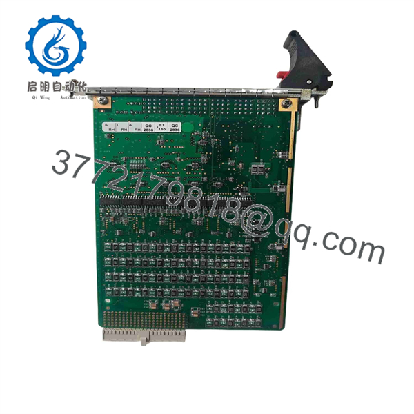
0190-37519
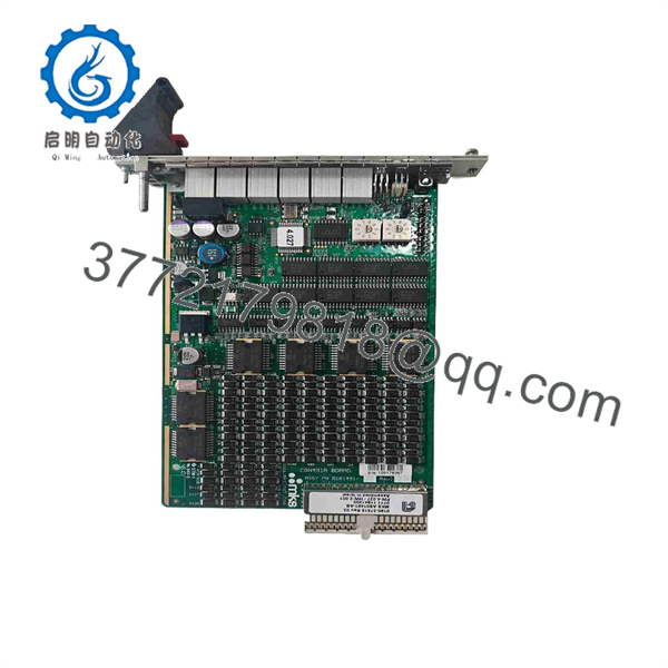
0190-37519
Stage 2: Removing the Old Module
- Verify electrical isolation.
- Remove the appropriate equipment cover.
- Photograph the installed board and connector positions.
- Label connectors where required.
- Disconnect cables carefully.
- Release the PCB retaining mechanism.
- Pull the board straight out of the card guides.
- Inspect the backplane connector for contamination or damaged contacts.
- Inspect the PCB for burned components, corrosion, cracked solder joints, or previous rework.
- Store the removed board in an ESD-safe bag.
⚠️ Keep the original PCB until the replacement passes the complete functional test.
Stage 3: Installing the New Module
- Establish ESD protection.
- Verify the replacement is Applied Materials 0190-37519.
- Confirm the board identification corresponds to MKS CDN491R / AS01491-AB where applicable.
- Compare the PCB revision against the removed board.
- Verify the intended rack/slot position.
- Align the PCB with the card guides.
- Insert the board evenly without excessive force.
- Engage the retaining hardware.
- Reconnect each cable according to the photographs and wiring documentation.
- Confirm all connectors are fully seated and locked.
- Restore shielding and grounding connections.
Self-Checklist
- 0190-37519 verified
- CDN491R identification verified
- AS01491-AB identification checked
- PCB revision recorded
- Rack/slot verified
- Connectors secured
- Grounding/shielding restored
- Original PCB retained
Stage 4: Power-On & Testing
- Perform a complete visual inspection.
- Confirm no tools or foreign objects remain inside the rack.
- Restore power according to the AMAT tool startup procedure.
- Observe PCB and system diagnostic indicators.
- Verify the controller recognizes the I/O subsystem.
- Check for new communication or I/O alarms.
- Verify analog input values against known process or simulated signals.
- Verify analog output commands where the service procedure permits controlled testing.
- Compare readings against the expected equipment values.
- Check for abnormal offsets, unstable readings, or out-of-range signals.
- Run the applicable AMAT equipment diagnostic.
- Perform required calibration before returning the tool to production.
⚠️ Do not inject arbitrary voltage or current into the I/O terminals. Determine the correct signal range and test method from the tool-specific documentation first.
Frequently Asked Questions (FAQ)
1. What is Applied Materials 0190-37519?
Applied Materials 0190-37519 is identified in multiple parts databases as an MKS CDN491R Analog I/O PCB. It is also cross-referenced with .
2. Is 0190-37519 a servo drive or motion-control module?
The stronger part-number evidence identifies it as the analog I/O PCB, not a generic servo drive. Some reseller pages publish conflicting descriptions, including motion-control and RF-interface claims. Those claims should not override the more consistent / identification.
3. What is the MKS equivalent part number?
The commonly cross-referenced MKS identification is . Listings also identify the board as .
4. Can I install any board as a replacement?
No. Match the 0190-37519 part number, board revision, connector arrangement, and AMAT equipment configuration.
A board that looks physically identical can still contain different revision hardware or configuration requirements.
5. Can I hot-swap 0190-37519?
Do not assume it is hot-swappable. Unless the specific AMAT tool documentation explicitly permits powered replacement, shut down and isolate the equipment first.
A standard PCB connector does not establish hot-swap capability.
6. Is 0190-37519 still available?
Specialist secondary-market inventory exists. Current listings show used examples, including listings specifically identifying the board as /.
Availability should be treated as inventory-dependent rather than assumed OEM production availability.
7. What condition should I specify when purchasing?
Be explicit:
- Factory Sealed
- New Original / New Surplus
- Refurbished and Tested
- Used / Tested
- Parts / As-Is
This distinction matters. Current marketplace listings include pre-owned units as well as parts-only, untested boards with missing or damaged components.
8. What should I provide to verify compatibility?
Provide:
- Applied Materials 0190-37519 part number
- MKS number, if visible
- board identification
- PCB revision
- AMAT equipment model
- Tool serial number
- Rack/slot location
- Clear photographs of the PCB and connectors
That information is much safer than selecting a replacement based only on the 0190-37519 number.



