
 WhatsApp: +86 16626708626
 Email:
  Phone: +86 16626708626
Description
Key Technical Specifications
| Parameter | Specification |
|---|---|
| Manufacturer | ASEM |
| Model | HT2150/S0 |
| Product Family | HT2150 |
| Architecture | Fanless Panel IPC |
| Processor | Intel Celeron J1900 |
| CPU Frequency | 2.00 GHz |
| CPU Cores / Threads | 4 / 4 |
| L2 Cache | 2 MB |
| Graphics | Intel HD Graphics, integrated |
| RAM | 1 GB to 8 GB DDR3 SODIMM |
| Storage | Bootable CFast SATA II + onboard mSATA SSD connector |
| Ethernet | 2 × 10/100/1,000 Mbps Intel I210 |
| USB | USB 3.0 and USB 2.0 |
| Power Supply | 24 VDC isolated |
| Operating Temperature | 0 to +50 °C |
| Front Protection | IP66 |
| Touchscreen | Configuration-dependent; resistive or other panel options |
| Add-On Interfaces | Optional; S0 supports additional interface installation |
| Remote Assistance | ASEM UBIQUITY |
The HT2150 family supports multiple display sizes and front-panel configurations. ASEM’s current product page lists 8.4″, 10.4″, 12.1″, and 15″ 4:3 displays, plus 7″, 10.1″, 12.1″, and 15.6″ widescreen options. Therefore, HT2150/S0 alone does not uniquely identify the display size or touchscreen configuration.
Older ASEM documentation specifies two Intel I210 Gigabit Ethernet ports, DDR3 memory up to 8 GB, CFast and mSATA storage, and a 0 to +50 °C operating range.
Product Introduction
The ASEM HT2150/S0 is a fanless industrial panel PC designed for HMI, machine visualization, industrial data acquisition, and control-system applications. It uses an Intel Celeron J1900 quad-core processor and an isolated 24 VDC power input.
The S0 configuration is distinguished by its ability to accept additional communication interfaces. Depending on the selected configuration, options include serial interfaces, additional USB, Gigabit Ethernet, wireless/modem functions, or a NETcore X fieldbus board.
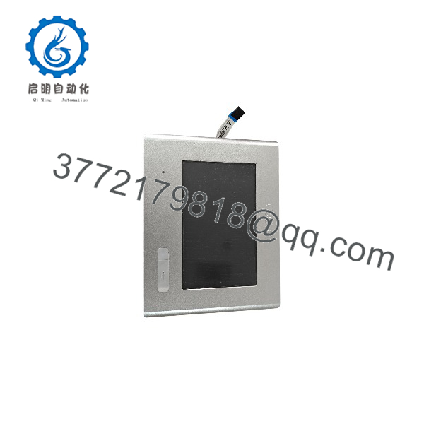
HT2150/S0
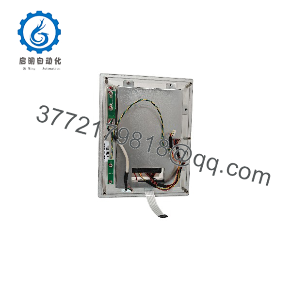
HT2150/S0
Installation & Configuration Guide
Stage 1 — Pre-Installation Preparation
Estimated time: 20–30 minutes
- Record the complete HT2150/S0 model and serial number.
- Confirm the installed display size and front-panel type.
- Record RAM, CFast/mSATA configuration, and installed expansion interface.
- Back up the existing HMI application and operating-system image.
- Verify the cabinet provides an isolated 24 VDC supply.
- Confirm panel cutout dimensions before removing the existing unit.
- Check that cabinet ambient temperature remains within the specified 0 to +50 °C range.
⚠️ Do not assume every /S0 has the same display or communication interfaces. Configuration must be checked against the unit being replaced.
Stage 2 — Removing the Existing Panel PC
Estimated time: 20–30 minutes
- Shut down the HMI/IPC through the installed operating system.
- Apply appropriate lockout/tagout procedures to the 24 VDC supply.
- Disconnect Ethernet, USB, serial, fieldbus, and other connected cables.
- Photograph connector locations before removal.
- Label cables where multiple identical connections are present.
- Release the panel mounting hardware.
- Remove the existing panel PC without damaging the cabinet cutout or gasket.
Stage 3 — Installing the /S0
Estimated time: 30–45 minutes
- Verify the mechanical cutout against the exact /S0 display configuration.
- Inspect the front-panel gasket and mounting surfaces.
- Insert the panel PC into the cabinet opening.
- Secure the mounting hardware evenly.
- Connect the isolated 24 VDC supply.
- Reconnect Ethernet and installed serial/USB/fieldbus interfaces.
- Install the CFast or mSATA storage device if the replacement unit does not already contain the required system image.
- Verify that no cable is under mechanical stress.
⚠️ Confirm DC polarity and supply voltage before energizing the IPC.
Stage 4 — Power-On & Testing
Estimated time: 30–60 minutes
- Energize the 24 VDC supply.
- Confirm normal BIOS/boot behavior.
- Verify the installed operating system loads correctly.
- Check touchscreen operation across the usable display area.
- Verify both Gigabit Ethernet ports.
- Test each installed optional communication interface.
- Launch the HMI application.
- Confirm communication with the PLC, controller, or field devices.
- Verify application startup behavior after a controlled restart.
- Record the final hardware configuration for future maintenance.
FAQ
1. What is the ASEM /S0?
It is a fanless industrial panel PC in ASEM’s family. It combines an integrated display/touch interface with an x86 industrial computer for HMI and automation applications.
2. What processor does the /S0 use?
The documented platform uses an Intel Celeron J1900, a quad-core 2.00 GHz processor with 2 MB L2 cache.
3. What is special about the S0 version?
The S0 version provides provisions for additional communication interfaces, unlike the reduced-depth SL configuration. Available options have included RS232/422/485, additional USB, Gigabit Ethernet, wireless/modem interfaces, and NETcore X fieldbus hardware.
4. What display size does /S0 use?
The model suffix alone is insufficient to determine the display size. The family was offered with several display formats and sizes. One documented /S0 configuration, for example, specifies a 6.5-inch TFT, while other S0 configurations use larger displays. Verify the complete configuration code and nameplate before ordering a replacement.
5. Does the /S0 have Ethernet?
Yes. Published specifications identify 2 × 10/100/1,000 Mbps Ethernet ports using Intel I210 controllers.
6. What power supply does it require?
The platform uses an isolated 24 VDC power input. Some documentation specifies an operating input range of 18–32 VDC for the 24 VDC supply configuration.
7. Is /S0 a direct replacement for another ?
Not necessarily. Display size, touchscreen technology, RAM, storage, operating system, and optional communication hardware can vary by configuration. For a direct replacement, compare the complete nameplate/configuration information and installed interface hardware, not just “/S0.”



