
 WhatsApp: +86 16626708626
 Email:
  Phone: +86 16626708626
Description
Key Technical Specifications
| Parameter | Value |
|---|---|
| Manufacturer | Autronica / Kongsberg Autronica |
| Part Number | 7251-005.0002 |
| Model | KMR-200 |
| Related System | KMR-200/600C |
| Product Type | PCB Card / Printed Circuit Board Module |
| Application | Marine monitoring system |
| Controller Platform | KMR-200 |
| Board Function | KMR-200 system PCB — exact circuit function should be verified from the system documentation |
| Installation | KMR-200 equipment |
| PCB Revision | Verify from physical board |
| Condition Available | New / uninstalled, used |
| Lifecycle | Legacy |
The available sources do not provide reliable electrical ratings, connector pinout, supply voltage, I/O count, or detailed circuit function for 7251-005.0002. Those specifications should not be inferred from other KMR-200 boards. Current listings identify the part as a PCB card/module but do not publish a complete technical datasheet.
Product Introduction
The Autronica 7251-005.0002 is a PCB card/module used in Autronica marine monitoring equipment. Current marine automation listings identify the part number directly with the platform and, in some listings, the /600C designation.
For replacement work, the complete part number is critical. Do not substitute another 7251-series PCB simply because the connector or board dimensions appear similar. Verify the board revision, connector arrangement, installed configuration, and original documentation before energizing the replacement.
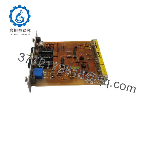
7251-005.0002
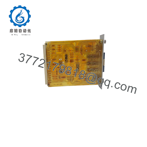
7251-005.0002
Installation & Configuration Guide
Stage 1: Pre-Installation Preparation — Approximately 10 Minutes
⚠️ Safety First: The is associated with marine monitoring equipment. Place the monitored system in its approved maintenance state before removing a PCB. Follow the vessel’s electrical isolation and permit-to-work procedures.
Tools Required:
- ESD wrist strap
- Digital multimeter
- Appropriate screwdriver
- Wire labels
- Smartphone or camera
- system documentation
Data Backup:
- Confirm the complete part number: 7251-005.0002.
- Record the equipment model and cabinet/rack position.
- Photograph the existing PCB from multiple angles.
- Photograph every connector before removal.
- Record board revision and identification markings.
- Document any LEDs, switches, jumpers, or configuration links.
- Record existing system alarms or diagnostic indications.
The supplied engineering procedure specifically recommends documenting configuration settings and photographing hardware before replacement.
Stage 2: Removing the Old PCB — Approximately 5–10 Minutes
- Isolate the equipment according to the approved procedure.
- Verify that hazardous voltages have been removed.
- Allow stored energy to discharge as specified by the equipment documentation.
- Label connected cables and connectors.
- Disconnect connectors by their locking mechanisms rather than pulling on wires.
- Release the PCB retaining hardware.
- Remove the board straight and carefully.
- Inspect the mating connectors and cabinet for corrosion, moisture, contamination, or bent contacts.
⚠️ Marine installations deserve extra inspection. Salt contamination and moisture can produce intermittent connector faults that look like a bad replacement board.
Stage 3: Installing the Replacement — Approximately 5–10 Minutes
- Wear a grounded ESD wrist strap.
- Verify the replacement marking: 7251-005.0002.
- Compare the board revision with the original.
- Confirm connector locations and mechanical orientation.
- Insert the PCB carefully without forcing the connector.
- Secure all retaining hardware.
- Reconnect each connector according to the photographs.
- Inspect the board once more before restoring power.
Self-Check:
- Correct 7251-005.0002 part number
- compatibility confirmed
- PCB revision checked
- Connectors correctly positioned
- Retaining hardware secured
- No visible corrosion or contamination
- ESD precautions maintained
Stage 4: Power-On & Testing — Approximately 10–20 Minutes
- Check applicable supply rails before energizing the equipment.
- Restore power according to the procedure.
- Observe the system startup sequence.
- Check PCB and system status indications.
- Verify that the recognizes the replacement board where applicable.
- Check for newly generated alarms.
- Confirm normal monitoring functions.
- Compare readings with known-good values or redundant instrumentation.
- Allow the system to operate under observation before closing the maintenance activity.
⚠️ If the replacement produces an unexpected alarm or communication fault, shut down according to the approved procedure and compare the board revision, connector seating, and configuration against the original.
Frequently Asked Questions (FAQ)
What is Autronica 7251-005.0002?
It is a PCB card/module used in Autronica marine monitoring equipment. Current listings explicitly associate part number 7251-005.0002 with .
Is 7251-005.0002 the same as a PCB?
Yes. Multiple current spare-parts records identify 7251-005.0002 as a PCB card or printed circuit board module.
Is /600C also associated with this part number?
Yes. One current product record describes 7251-005.0002 as a printed circuit board and identifies the system as .
Can I replace 7251-005.0002 with another PCB?
Do not assume that. equipment can contain multiple PCB types, and similar boards may have different functions. The safest replacement criterion is the complete 7251-005.0002 part number plus compatible board revision.
Is 7251-005.0002 still available?
Yes, it remains available through the marine automation spare-parts market. Current listings show both new/uninstalled and used units. Availability is limited and condition varies by supplier.
What electrical specifications should I verify before buying?
For this specific PCB, verify the board revision, connector arrangement, supply requirements, mounting configuration, and exact system compatibility. Public listings reviewed do not provide sufficient evidence for reliable voltage, current, I/O, or communication specifications.
What condition should I request?
For a critical marine spare, specify the condition explicitly: new/uninstalled, new surplus, or refurbished/tested. Request photographs of the actual PCB, including its part number and revision markings. Current listings demonstrate that the same part number is sold in materially different conditions.



