
 WhatsApp: +86 16626708626
 Email:
  Phone: +86 16626708626
Description
3. Key Technical Specifications
| Parameter | Value / Description |
|---|---|
| Manufacturer | Autronica Fire and Security |
| Full Model | MGA-5A-12-B-15-GT-7 |
| Product Category | Gas detection / multi-gas alarm interface module |
| Typical Application | Marine, offshore, or industrial fixed gas detection systems |
| System Compatibility | Autronica gas detection platforms (exact match requires system drawings) |
| Configuration Coding | Part number encodes channel count, range, sensor type, and options |
| Mounting | Panel, DIN-rail, or enclosure mount (confirm on unit) |
| Power Supply | System-dependent (typically 24 V DC range – verify nameplate) |
| Signal Interface | Analog (4–20 mA) and/or discrete alarm contacts (typical for series) |
| Environment | Industrial / marine conditions |
| Condition Note | Units are configuration-specific; do not assume interchangeability without verification |
Exact electrical ratings, terminal assignments, sensor ranges, and software/firmware versions must be confirmed against the physical unit nameplate, internal documentation, or the original Autronica project drawings. Public datasheets for this precise long-form part number are not widely available.
4. Product Introduction
The Autronica MGA-5A-12-B-15-GT-7 is a configuration-specific gas detection module or interface unit used within Autronica fixed gas detection and alarm systems. The long part number encodes the particular channel arrangement, measurement range, sensor interface type, and option set required for a given installation.
These modules appear in marine, offshore, and industrial fire-and-gas systems that still run older or customized Autronica gas detection architectures. The unit is selected when a direct hardware replacement is needed to restore system functionality without redesigning the entire detection loop or control panel.
5. Installation & Configuration Guide
Stage 1: Pre-Installation Preparation (≈15–20 min) ⚠️ Safety First: Coordinate with the control room / bridge. Isolate power to the gas detection cabinet and any associated detector loops. Apply full lock-out/tag-out. Confirm the affected detection zones are under temporary manual watch if required by the vessel or plant safety procedures. Tools Required: ESD wrist strap, multimeter, insulated screwdrivers, wire markers, camera. Documentation: Photograph every terminal connection, any DIP switches or jumpers, and the existing module’s nameplate. Record the exact part number and any calibration or range labels. Export or note current alarm set-points from the system if accessible.
Stage 2: Removing the Old Module (≈10 min)
- Verify zero voltage on all terminals.
- Label every wire and connector before disconnection.
- Release mounting hardware or DIN-rail clips and withdraw the module carefully.
- Inspect connectors and backplane/terminals for corrosion or bent pins. ⚠️ Keep the original module available until the replacement has completed full functional testing.
Stage 3: Installing the New Module (≈15 min)
- Confirm the incoming MGA-5A-12-B-15-GT-7 matches the removed unit’s full part number and any visible configuration labels.
- Configuration Clone (Critical): Set any accessible switches, jumpers, or address settings exactly as photographed. Do not assume factory defaults are correct for the system.
- Seat the module fully and secure mounting hardware.
- Reconnect all wiring according to the labeled scheme and original drawings. Self-Checklist: [ ] Part number matches [ ] Switches/jumpers cloned [ ] Terminals secure [ ] No pinched wires.
Stage 4: Power-On & Testing (≈20–40 min) Pre-Power Check: Continuity and insulation resistance on detector and alarm circuits. Power-On Steps:
- Restore power and observe module status indicators.
- Verify communication with the main panel or controller if applicable.
- Perform a detector simulation or apply test gas (per site procedure) and confirm correct reading and alarm escalation at the required set-points.
- Test fault monitoring (open/short simulation) if the system supports it.
- Document results for the safety management system. ⚠️ Troubleshooting Note: Incorrect address, range coding, or 4–20 mA polarity are the most frequent causes of “wrong gas reading” or missing alarms after a module swap. Always cross-check against the system’s approved drawings.
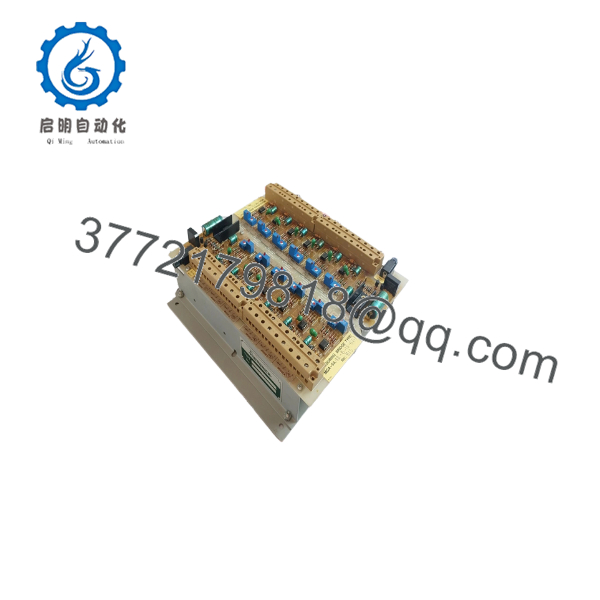
MGA-5A-12-B-15-GT-7
6. Frequently Asked Questions (FAQ)
Q: Can this module be hot-swapped under power? No. Isolate power and detector circuits before removal or installation. Live replacement risks false alarms, equipment damage, or personal injury.
Q: Is the MGA-5A-12-B-15-GT-7 still in current production? This appears to be a configuration-specific or legacy Autronica part. Available units are typically new surplus or carefully tested secondary-market stock. Exact production status should be confirmed with the supplier.
Q: Can I substitute a different MGA-5A variant? Only if the full part number (including all suffixes) and the system drawings confirm functional and electrical equivalence. Channel count, range, sensor type, and option codes differ between variants. Incorrect substitution can produce wrong readings or failed alarms.
Q: Will I lose calibration or configuration data? Any module-specific calibration or address settings reside in the hardware. Record all settings before removal and transfer them to the replacement unit. System-level set-points may need re-verification after the swap.
Q: Why is the price lower than a modern Autronica gas system? These are surplus or secondary-market modules intended to maintain existing installations, not current-production replacements. Pricing reflects condition, testing, residual demand, and the cost of independent verification rather than OEM new-equipment pricing.
Q: What documentation should accompany the unit? Request the supplier’s functional test report, photographs of the nameplate, and confirmation that the exact part number MGA-5A-12-B-15-GT-7 matches the required configuration. Cross-check against the vessel or plant’s approved drawings before installation.
Q: What is the most common installation error? Assuming all MGA-series modules are interchangeable. Always match the complete part number and verify signal type, range, and wiring against the original installation documentation.



