
 WhatsApp: +86 16626708626
 Email:
  Phone: +86 16626708626
Description
Key Technical Specifications
| Parameter | Specification |
| Module Type | Terminal Connection Card / Wiring Interface Unit |
| System Compatibility | Autronica NK Series & BS Series Marine Control Racks |
| I/O Termination | Multi-pin screw terminal blocks for field sensor wiring |
| Backplane Interface | Multi-way edge connector for direct rack bus insertion |
| Operating Voltage | 24 V DC system bus rating |
| Operating Temp | -10°C to +70°C (standard marine environments) |
| Mounting Format | Rack-mounting plug-in circuit board |
| Enclosure Rating | Open PCB for chassis panel integration |
Product Introduction & Supply Chain Strategy
The Autronica NKL-6 is a terminal connection module engineered for marine monitoring systems and safety alarm panels. It serves as the physical interface bridge between external field wiring—such as pressure sensors, temperature detectors, and alarm loops—and the internal processing backplane of the control chassis.
Sourcing this module as New Surplus ensures immediate operational readiness during urgent ship calls, preventing long factory lead times for obsolete legacy components. Choosing New Surplus over high-risk refurbished boards eliminates hidden copper track oxidation and loose, stressed screw terminals, ensuring high system uptime while maintaining low Total Cost of Ownership (TCO).
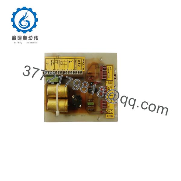
NKL-6
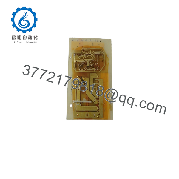
NKL-6
Installation & Configuration Guide
Stage 1: Pre-Installation (Prep & Safety)
- Disconnect all 24 V DC power sources to the monitoring rack following standard LOTO safety procedures.
- Put on a grounded ESD wrist strap connected to the grounded panel metal enclosure.
- Label every field conductor connected to the existing terminal blocks and take clear photos of the wiring arrangement.
Stage 2: Removal
- Loosen screw terminals to release individual field wires, or disconnect removable terminal blocks if equipped.
- Unfasten any board locking latches or panel retaining screws holding the card in place.
- Pull the NKL-6 board straight out from the card guide rails to prevent bending rear backplane connector pins.
Stage 3: Installation (Clone & Seat)
- Inspect the new NKL-6 board to confirm physical match and jumper configuration parity with the original unit.
- Align the card edges within the guide rails and push firmly until the backplane connector locks into the socket.
- Reattach field wiring to the corresponding screw terminals based on previously recorded circuit labels.
Stage 4: Power-On & Testing
- Re-energize the 24 V DC power bus and monitor system power indicators for stable operation.
- Perform loop continuity and signal verification across connected field sensors to ensure proper alarm communication.
Firmware/Software Versions & Upgrade Notes
- Hardware Revisions: Confirm the variant suffix matches your panel documentation to ensure proper connector keying and trace continuity.
- Compatibility Notice: The NKL-6 is a passive interface card; however, incorrect wiring pinouts will misroute analog or digital sensor signals to processing cards, causing false system faults.
- Handling Warning: Do not apply access force when tightening screw terminals. Over-tightening can fracture the solder pad bond between the terminal block and the circuit board.
Frequently Asked Questions (FAQ)
Q: Is this Autronica NKL-6 board genuine New Surplus?
A: Yes. This module is 100% New Surplus / Original New stock. It has never been installed in a marine cabinet, pulled from a decommissioned vessel, or subjected to field repairs.
Q: Why pay slightly more for New Surplus instead of a refurbished NKL-6?
A: Refurbished connection boards frequently suffer from fatigue in screw terminal threads, hairline PCB cracks, or pin corrosion from salt-air exposure. New Surplus guarantees original physical integrity, reliable electrical contact, and long operational life without risk of intermittent signal faults.
Q: How do you verify the quality of legacy connection boards before shipping?
A: Every board undergoes rigorous visual pin inspection, terminal thread checks, and electrical continuity testing across all terminal-to-connector pathways prior to ESD packaging.
Q: Can I connect field wiring to the while the system is powered?
A: No. Always de-energize system power before wiring or handling the card to prevent accidental short circuits across input channels or control backplanes.
Q: What warranty is offered with this item?
A: We provide a full 1-year replacement warranty on all New Surplus inventory. If the module exhibits any defect during normal operation, we will replace it immediately or process a credit.



