
 WhatsApp: +86 16626708626
 Email:
  Phone: +86 16626708626
Description
Key Technical Specifications
| Parameter | Value |
|---|---|
| Model | Autronica NLA-2A |
| Alternate part designation | NLA-2/A |
| Reference number | 50022-264 |
| Product type | Common alarm control unit / alarm control PCB |
| Associated systems | Autronica NL-4 and GL-7 |
| Primary function | Common alarm control and alarm-test operation |
| Application | Marine alarm and monitoring systems |
| Supply voltage | Not verified from available public listings |
| Input/output configuration | Not verified; confirm from the installed system schematic |
| Alarm-test function | Referenced by supplier listings; verify exact front-panel and relay functions |
| Connector pinout | Not verified; match the board revision and terminal designation |
| Dimensions | Not verified from available public listings |
| Listed weight | Approximately 300 g in one supplier listing; verify packed and actual unit weight |
| Operating temperature | Not verified from available public listings |
| Condition | Supplier-specific; current listings include used and surplus units |
| Availability | Legacy marine spare; stock varies by supplier |
Current listings identify the Autronica NLA-2A as an alarm control module or common alarm unit. A Kongsberg Autronica listing associates it with NL-4 and GL-7 systems, while another listing identifies reference number 50022-264. Available sources do not provide a complete OEM datasheet for supply voltage, relay ratings, terminal pinout, or environmental limits.
Product Introduction
The Autronica NLA-2A is a common alarm control module used in Autronica marine alarm systems, including NL-4 and GL-7 installations. It handles common alarm and alarm-test functions within the system architecture.
This legacy module must be matched by complete part marking, reference number, system type, connector layout, and PCB revision. Verify the vessel’s wiring diagram and alarm matrix before installation; NLA-2A is not a universal replacement for every Autronica alarm-control board.
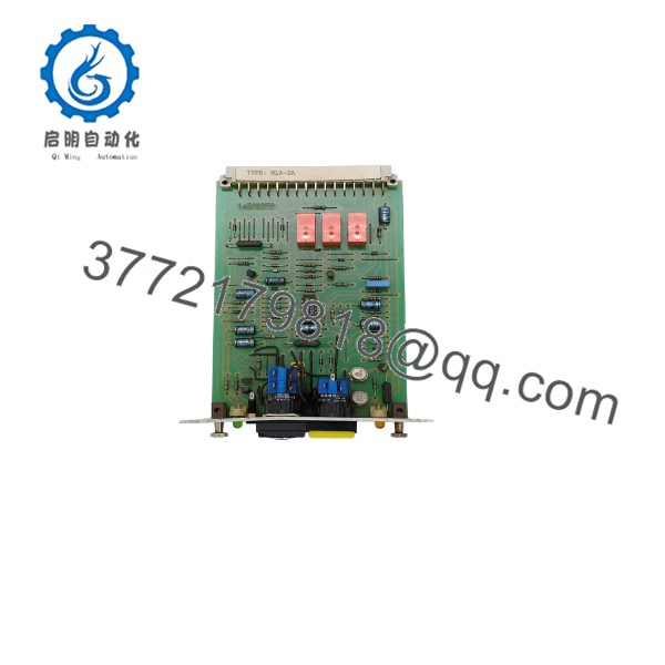
NLA-2A
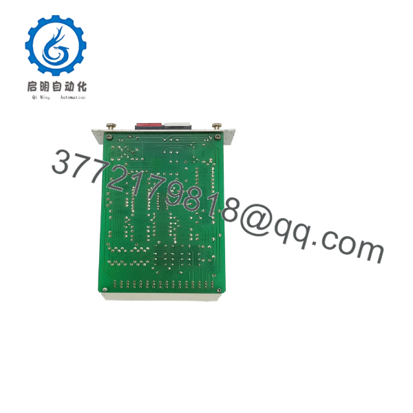
NLA-2A
Troubleshooting Quick Reference
| Symptom | Possible Cause | Relevance to This Part | Quick Check Method | Recommendation |
|---|---|---|---|---|
| No alarm indication | Missing supply, open fuse, loose connector, or failed control module | ✅ Medium | Measure supply voltage directly at the NLA-2A input terminals using the vessel schematic | Check power and connector seating before replacing the module |
| Common alarm remains active | Field alarm, latched relay, reset circuit fault, or NLA-2A logic failure | ✅ High | Review active alarm channels and measure the common alarm relay state during reset | Clear the initiating alarm first; replace the module only if the relay remains incorrect |
| Alarm-test button has no effect | Failed test switch, open wiring, missing supply, or internal input fault | ✅ High | Operate the approved test control and measure the input voltage or contact change at the module | Check the switch and wiring before condemning the PCB |
| Alarm-test operates but remote alarm does not | Open cable, wrong relay contact, downstream panel fault, or terminal mismatch | ❌ Low to medium | Measure relay contact continuity during a controlled alarm test | Troubleshoot the external alarm circuit before replacing |
| Audible alarm does not sound | Alarm buzzer, horn circuit, relay contact, fuse, or external wiring fault | ❌ Low to medium | Check whether the relay changes state, then test the horn circuit separately | Replace the sounder or repair field wiring if the relay operates correctly |
| Reset does not clear the alarm | Stuck alarm input, faulty reset circuit, incorrect common, or failed module input | ✅ Medium | Verify reset signal voltage and inspect whether the initiating alarm remains active | Correct the initiating circuit before replacing the control module |
| False common alarms occur | Noise, moisture, loose terminal, contact bounce, or wrong board variant | ✅ Medium | Monitor the input and supply voltage while inspecting connectors and alarm contacts | Inspect wiring, grounding, and moisture before replacing the unit |
| NL-4 or GL-7 does not recognize the module | Wrong part number, revision mismatch, connector problem, or system fault | ✅ High | Compare the module label, reference number, connector keying, and system slot location | Use an exact system-compatible replacement |
| Behavior changes after replacement | Incorrect jumper, switch, relay logic, or terminal wiring | ✅ High | Photograph both modules and compare all links, labels, and contact designations | Never wire from memory; verify every terminal against the schematic |
| Intermittent alarm operation | Vibration, cracked solder joint, oxidized connector, or unstable supply | ✅ Medium | Inspect under magnification and perform a controlled continuity and supply-voltage check | Repair the connection or replace the module after confirming the fault |
| Board handled without ESD protection | Latent electronic damage | ✅ Medium | Perform a controlled alarm-test sequence after inspecting the PCB | Use a grounded wrist strap and ESD-safe handling procedures |
Support note: If the fault remains, contact technical support with photos of the module label, reference number, PCB revision, terminal wiring, system type, alarm logs, and measured supply and relay voltages.
Frequently Asked Questions
What does the Autronica do?
The is an Autronica alarm control module used for common alarm and alarm-test functions in marine alarm systems. Listings associate it with NL-4 and GL-7 systems.
Is the same as NLA-2/A?
Listings use both designations, but verify the actual board marking and reference number before purchasing. One distributor identifies NLA-2/A as the related board designation, while other listings use .
Is reference number 50022-264 interchangeable with every ?
Do not assume that it is. Reference number 50022-264 appears in an listing, but compatibility still depends on the NL-4 or GL-7 system version, connector arrangement, PCB revision, and alarm logic.
Can I hot-swap the ?
Treat it as non-hot-swappable unless the specific Autronica documentation authorizes live removal. Isolate the supply, follow the vessel’s lockout/tagout procedure, and confirm that alarm coverage remains controlled during the replacement.
Will replacing the module preserve alarm settings?
Not necessarily. The alarm matrix, relay logic, jumpers, switches, or external configuration may determine system behavior. Photograph the original unit, record every link and terminal, and perform a complete alarm-test sequence after installation.
Is the Autronica obsolete?
It should be treated as legacy equipment with limited availability. Current listings show used, surplus, and specialist-stock units rather than clear current-production availability. Request exact photos and test evidence before placing an order.
What should the supplier test before shipping?
Request a visual inspection, connector check, power-up test, alarm-test input verification, common-alarm relay test, reset test, and confirmation of the exact NL-4 or GL-7 test environment. Require the condition in writing as New Original (New Surplus), Factory Sealed, or Refurbished (tested), along with warranty and return terms.



