
 WhatsApp: +86 16626708626
 Email:
  Phone: +86 16626708626
Description
Key Technical Specifications
| Parameter | Specification |
| Manufacturer | Bartec |
| Part Number | 07-7331-23040000 |
| Product Line | Explosion-Proof Fieldbus Interface |
| Explosion Protection | ATEX / IECEx Zone 1, Zone 2, Zone 21, Zone 22 |
| Type of Protection | Ex d [ia/ib] IIC T6 / Flameproof Enclosure |
| Operating Voltage | 24 VDC (18 to 30 VDC input range) |
| Communication Protocol | PROFIBUS DP (up to 1.5 Mbps / RS-485 IS) |
| Channel Capacity | Integrated Field I/O Interface |
| Ambient Temperature | −20°C to +60°C |
| Housing Material | Heavy-duty impact-resistant polymer / aluminum enclosure |
| Ingress Protection | IP65 / IP66 Rated |
Product Introduction & Supply Chain Strategy
The Bartec 07-7331-23040000 is an explosion-proof fieldbus interface and I/O module designed for hazardous process environments. It functions as an intrinsically safe PROFIBUS DP node, connecting field sensors, valves, and actuators located in Zone 1 or Zone 2 hazardous areas directly to central DCS or PLC control networks.
In chemical plants, offshore oil platforms, and refineries, an I/O fieldbus failure can trigger automated safety shutdowns and halt continuous process loops. Installing a refurbished or repaired module in an Ex environment exposes your plant to unseen enclosure seal degradation, damaged flameproof paths, and degraded internal zener barrier safety components. Keeping a genuine New Surplus 07-7331-23040000 unit in your critical spare inventory guarantees full ATEX compliance, zero operating hours, and immediate restoration during unexpected field bus dropouts.
Installation & Configuration Guide
1.Stage 1: Pre-Installation (Prep & Safety):Hot-Work Permit & LOTO.
- Obtain a certified Hot-Work Permit and verify zero explosive gas presence using a calibrated gas detector.
- Perform complete Electrical Lock-Out/Tag-Out (LOTO) on the 24 VDC power feed and fieldbus segment.
- Inspect the outer flameproof housing and gland threads of the 07-7331-23040000 unit for transit damage.
- Record the DIP switch settings (PROFIBUS node address and bus termination status) from the existing field module.
2.Stage 2: Removal:Enclosure Decoupling.
- Unscrew Ex-d certified cable glands carefully to prevent damaging the thread pitch or sealing rings.
- Disconnect the 24 VDC power terminals, shielding wire, and RS-485 fieldbus connector lines.
- Unbolt the mounting fasteners and extract the module from the field junction cabinet.
3.Stage 3: Installation (Clone & Seat):Mechanical Seating & Cloning.
- Set the PROFIBUS node address DIP switches on the new module to mirror the removed unit exactly.
- Secure the 07-7331-23040000 module onto the enclosure DIN-rail or backplate mounting bolts.
- Reattach cable conductors ensuring proper torque on terminal screws; verify the RS-485 shield ground continuity.
- Tighten Ex cable glands to maintain certified flameproof sealing and preserve IP66 ingress protection.
4.Stage 4: Power-On & Testing:Bus Verification & Commissioning.
- Apply 24 VDC power and observe the status LEDs for healthy power-on self-test indications.
- Check that the PROFIBUS DP “BF” (Bus Fault) LED turns OFF, confirming successful handshake with the master controller.
- Verify real-time analog and digital field values inside the DCS/PLC hardware manager before closing the enclosure cover.
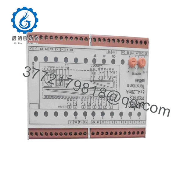
07-7331-23040000
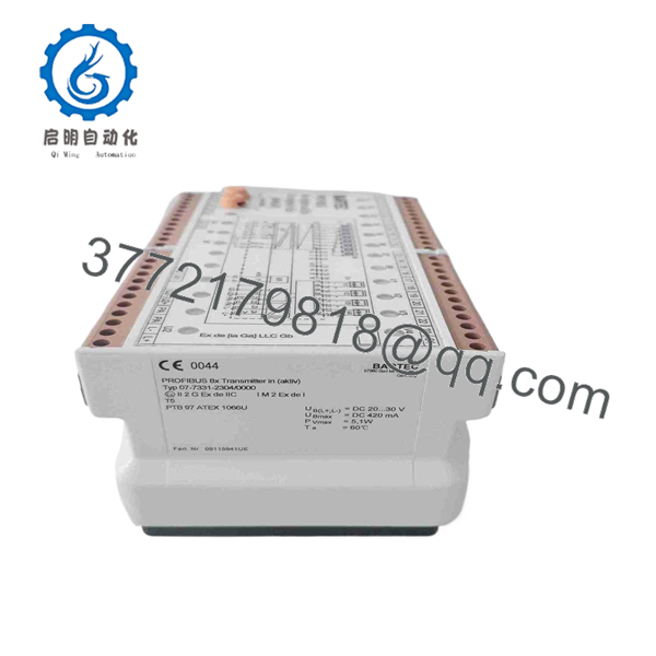
07-7331-23040000
Firmware/Software Versions & Upgrade Notes
- GSD File Integration: Ensure the master PLC/DCS configuration tool utilizes the exact matching Bartec GSD file revision for model
07-7331-23040000. Mismatched GSD configurations can lead to parameterization faults (Prm_Fault) or cyclic data exchange rejections. - Baud Rate Restrictions: While the module supports standard PROFIBUS DP communication up to 1.5 Mbps, long field cables in hazardous zones with intrinsically safe repeaters should be limited to 187.5 kbps or 500 kbps to eliminate signal reflection errors.
- Bus Termination: Verify active bus termination switches at the physical end of the fieldbus segment. Double-terminating or omitting termination on an RS-485 IS line causes erratic frame drops across neighboring nodes.
Frequently Asked Questions (FAQ)
Q: Why should we purchase a New Surplus Bartec module instead of a refurbished unit?
A: Equipment installed in hazardous locations (ATEX/IECEx) must maintain uncompromised internal flameproof paths, intact potting, and tested zener barrier components. Refurbished units carry risks of invisible static discharge damage, compromised housing gaskets, and degraded component safety margins. Our New Surplus inventory delivers factory-fresh reliability, ensuring absolute compliance and safety.
Q: Is this 07-7331-23040000 module guaranteed to be genuine Bartec manufacture?
A: Yes. All inventory is guaranteed authentic Bartec original production. Each module undergoes rigorous physical inspection, continuity testing, and power-on verification prior to shipment.
Q: Can this module be installed directly in Zone 1 hazardous areas?
A: Yes, the 07-7331-23040000 is engineered with explosion-proof and intrinsically safe protection ratings suitable for Zone 1 and Zone 2 hazardous gas atmospheres, provided installation adheres to OEM gland and enclosure guidelines.
Q: Can I hot-swap this fieldbus interface while field power is active?
A: Hot-swapping inside a hazardous location is strictly prohibited unless a gas-free clearance certificate is active or the circuit is certified intrinsically safe (Ex i) for live maintenance. Always isolate cabinet power before opening non-intrinsically safe enclosures.
Q: Does this module store PLC application logic or network parameters?
A: No. The unit operates as a slave fieldbus interface. The hardware node address is configured physically via DIP switches, while operational logic, I/O mapping, and bus cycle timing are managed entirely by the host controller PLC/DCS.
Q: What warranty coverage is provided with this New Surplus unit?
A: We provide a full 1-Year Comprehensive Replacement Warranty. If any operational defect occurs within 12 months under standard operating conditions, we will replace the unit or issue a full refund.



