
 WhatsApp: +86 16626708626
 Email:
  Phone: +86 16626708626
Description
Key Technical Specifications
| Parameter | Value |
|---|---|
| Manufacturer | Basler Electric |
| Model | DECS-200-1L |
| Product Family | DECS-200 Digital Excitation Control System |
| Product Type | Digital automatic voltage regulator and excitation controller |
| Basler Part Number Reported | 9360100101 |
| Primary Application | Synchronous generator and motor excitation control |
| Supported Field Applications | 32 V DC, 63 V DC, or 125 V DC field systems |
| Maximum Field Output | Up to 15 A DC |
| Listed AC Input/Sensing Range | 56–277 V AC; verify against the exact unit label and manual |
| Voltage Regulation Accuracy | 0.25% reported |
| Sensing Method | True RMS; single-phase or three-phase sensing |
| Control Modes | Automatic voltage regulation and field-current/manual regulation |
| Generator Control Functions | Voltage, VAR, power-factor, and load-sharing control functions |
| Limiting Functions | Underfrequency/V/Hz compensation, minimum excitation limiting, maximum excitation limiting, and stator-current limiting |
| Dynamic Response Hardware | Pulse-width-modulated power stage |
| Setup Interface | Front-panel HMI or PC configuration software |
| Stability Settings | 20 standard stability selections plus user-customizable selection |
| Monitoring Functions | Exciter diode monitoring, sequence-of-events recording, and oscillography |
| 1L Variant Feature | Internal auto-tracking and 24/48 V DC power supply reported |
| Certifications Reported | UL Recognition, CSA, and CE |
| Lifecycle Status | Discontinued; Basler recommends the DECS-250 family as a newer product line |
Basler identifies the DECS-200 as discontinued and directs users to the DECS-250 as the recommended newer product family. Product references for the DECS-200-1L identify support for 32 V DC, 63 V DC, and 125 V DC excitation applications up to 15 A DC; 0.25% voltage regulation; true-RMS single- or three-phase sensing; and PC or front-panel setup. The 1L version is reported to include internal auto-tracking and a 24/48 V DC power-supply feature.
Product Introduction
Basler Electric DECS-200-1L is a microprocessor-based digital excitation control system for synchronous generators and motors. It regulates terminal voltage by controlling field current and supports generator protection, VAR or power-factor control, voltage matching, paralleling functions, and event analysis functions in one excitation package.
The DECS-200-1L supports field applications at 32 V DC, 63 V DC, or 125 V DC with up to 15 A DC output. It is a configured excitation-system component, not a plug-and-play voltage regulator. Match the generator field data, PT/CT sensing, operating mode, firmware, site settings, and all external interfaces before replacement.
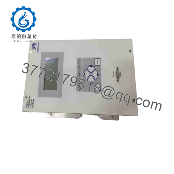
DECS-200-1L
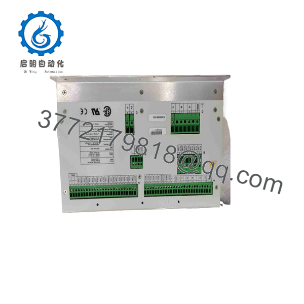
DECS-200-1L
Troubleshooting Quick Reference
| Symptom | Possible Cause | Relevance to This Part | Quick Check Method | Recommendation |
|---|---|---|---|---|
| DECS display is blank or controller will not power up | Missing auxiliary control power, open fuse, incorrect DC supply polarity, loose terminal, damaged wiring, or failed controller | ✅ High | With the unit isolated as required, measure the specified auxiliary supply directly at the DECS power terminals. Confirm polarity and compare with the exact wiring diagram. | Check fuses, supply voltage, grounding, and terminals before replacing -1L. |
| Generator voltage does not build | Residual magnetism loss, open field circuit, field breaker open, incorrect AVR mode, failed rotating exciter, missing sensing voltage, incorrect settings, or failed DECS output stage | ✅ High | Verify the field breaker state, field continuity, generator terminal voltage sensing, and measured field current. Use the approved excitation-system commissioning procedure. | Do not force field voltage without an approved procedure. Rule out generator/exciter hardware before replacing the controller. |
| Generator voltage is too low | Voltage reference set low, underfrequency limiter active, field current limit active, sensing ratio error, exciter problem, low prime-mover speed, or field-circuit fault | ✅ High | Compare actual generator frequency, terminal voltage, voltage reference, field current, and DECS active-limiter status. Confirm PT ratio configuration. | Correct speed or sensing configuration first. A low-voltage condition often originates outside the regulator. |
| Generator voltage is too high | Incorrect sensing wiring, voltage-reference error, failed feedback circuit, reverse control action, wrong PT ratio, improper manual-mode setting, or failed power stage | ✅ High | Transfer to a safe operating condition per site procedure. Compare displayed sensed voltage with a calibrated meter at generator terminals. Review configured PT ratio and control mode. | Do not keep the generator online with uncontrolled overvoltage. Investigate sensing and field-control wiring immediately. |
| Field current remains at maximum | Manual field-current mode active, sensing input missing, open PT fuse, incorrect control polarity, wrong settings, shorted output stage, or generator fault | ✅ High | Check mode indication and active alarms. Verify measured sensing voltage at DECS terminals and inspect PT fuses. Compare commanded field current with actual current. | Treat maximum excitation as a protection concern. Remove the generator from service safely and diagnose before cycling power. |
| Unit alarms on loss of sensing or abnormal voltage | Blown PT fuse, disconnected sensing lead, wrong phase connection, loose terminal, incorrect sensing configuration, or damaged input circuit | ✅ Medium | Measure all configured sensing voltages at the DECS terminals using the approved metering method. Verify phase order and neutral/reference wiring. | Replace fuses or correct wiring before considering controller replacement. |
| Generator will not share reactive load | Incorrect VAR/PF settings, CT polarity issue, wrong CT ratio, missing paralleling connection, load-share line fault, or incompatible settings between regulators | ✅ Medium | Review reactive power, power factor, CT phase/polarity, configuration files, and active control mode. Compare units in parallel operation. | Verify CT wiring and settings first. A reversed CT is a classic cause of unstable or incorrect reactive load sharing. |
| Oscillation or hunting occurs | Poor stability settings, incorrect generator model data, weak prime mover, loose sensing connection, bad PT/CT wiring, nonlinear load effect, or exciter/field issue | ✅ Medium | Record voltage, frequency, field current, and VAR trends. Use the DECS event/oscillography tools where enabled. Confirm wiring integrity and generator condition. | Adjust stability only using the approved commissioning method. Do not make random gain changes on an online generator. |
| Unit trips during load steps | Stator-current limiter, maximum excitation limiter, underfrequency limiter, field overcurrent, voltage dip, generator fault, or load transient beyond settings | ✅ Medium | Retrieve the sequence-of-events record and oscillography before resetting. Correlate timestamp with breaker, load, engine/turbine, and protection records. | Diagnose the initiating event. The DECS trip may be responding correctly to an upstream or generator condition. |
| No PC communication | Incorrect communication port selection, wrong cable, incorrect protocol or port settings, missing driver, PC software mismatch, or controller communication issue | ❌ Low to Medium | Verify the physical port, cable pinout, selected COM port, baud rate, PC interface adapter, and installed Basler setup software version. | Test with a known-good cable and approved laptop configuration before replacing the controller. |
❗ Generator excitation is not routine 24 V DC I/O work. Incorrect changes to voltage sensing, CT polarity, field wiring, limiter values, or control mode can trip a generator, damage a rotating exciter, create severe overvoltage, or destabilize parallel operation. Only qualified generator-control personnel should commission or modify the -1L.
❗ Back up settings before removal. Save the complete configuration file, event history, oscillography, setpoints, PT and CT ratios, stability values, limiter settings, active mode, serial/communication settings, and firmware identification. A replacement can power up correctly but behave incorrectly with default parameters.
❗ Do not confuse voltage sensing with field power. The uses sensing and field-control circuits that must be landed exactly as designed. A wrong PT phase, missing neutral reference, or open sensing fuse can make a healthy regulator drive the field in the wrong direction.
❗ Check the machine before blaming the AVR. Loss of residual magnetism, open field windings, failed rotating diodes, bad brushgear where applicable, poor generator speed, and PT fuse failures can all imitate a failed excitation controller.
If you need support, provide the complete -1L nameplate photo, generator rating plate, excitation single-line diagram, terminal photos, measured generator voltage and frequency, field voltage/current readings, active alarm text, event report, oscillography file, and current configuration backup.
Frequently Asked Questions (FAQ)
What is?
is a digital excitation control system, often called a digital AVR, for synchronous generators and motors. It regulates terminal voltage through field-current control and provides control, limiting, protection, monitoring, and reactive-load-management functions.
The unit is used in generator packages, utility auxiliary generation, industrial plants, marine power systems, and other installations requiring controlled excitation.
obsolete?
Yes. Basler lists the product as discontinued and identifies the DECS-250 as a recommended newer product family. That does not mean every installed must be replaced immediately. For an outage repair, an exact spare may still be the least-risk option. For a planned modernization, evaluate DECS-250 compatibility, field wiring, sensing, communications, parameter conversion, cabinet layout, and commissioning requirements.
What does “1L” ?
The 1L suffix distinguishes a specific configuration. Product references repo includes internal auto-tracking and a 24/48 V DC power-supply feature. Do not assume that other variants have the same auxiliary power arrangement, tracking features, or interface configuration.
Match the complete nameplate, not only the family designation.
What excitation out support?
Available product references state t can accommodate 32 V DC, 63 V DC, or 125 V DC excitation applications at up to 15 A DC. Confirm the actual generator-field requirement and system wiring with the Basler manual before replacement. Field voltage, field current, exciter configuration, and forcing requirements determine whether the unit is correct for the machine.
Can I with any automatic voltage regulator?
No. A generic AVR is not a safe direct repla combines voltage regulation with field-current control, VAR/PF control, load sharing, protective limiters, event recording, oscillography, sensing configuration, and system-specific logic.
A substitute must be engineered and commissioned for the exact generator, exciter, PT/CT circuits, protection philosophy, control interfaces, and parallel-operation scheme. Basler’s DECS-250 is a newer family recommendation, but it should be treated as a migration project, not an overnight card swap.
Will the generator settings transfer to a replacement controller?
Not automatically. You must back up and validate the parameter file from the installed controller. Record voltage references, PT and CT ratios, sensing mode, stability values, limiter curves, underfrequency settings, field-current limits, VAR/PF settings, paralleling configuration, alarm logic, communications, and firmware information.
Do not download settings blindly to a replacement. First verify that the target unit is the same hardware variant and firmware generation. Then review each setting against the generator’s approved commissioning record.
Can I h?
No. Do not hot-swap an excitation controller. Removing it while energized can interrupt field current, create a generator trip, cause a voltage excursion, damage contacts or wiring, and create a dangerous condition for people and connected equipment.
Coordinate with operations. Remove the generator from service or place it in an approved safe condition, open and isolate the relevant AC and DC supplies, discharge stored energy, verify zero voltage, and follow site generator-control procedures before replacement.
Why does the generator have no voltage even powers up?
A powered controller does not prove the excitation system is healthy. Common causes include an open field breaker, lost residual magnetism, blown PT sensing fuses, an open field winding, failed rotating rectifier diodes, incorrect sensing wiring, low engine/turbine speed, field flash requirement, or disabled control mode.
Start with the excitation single-line diagram. Confirm generator speed and frequency, sensing voltage, field continuity, field current, breaker states, and active alarms. Do not attempt field flashing or manual excitation unless the OEM procedure and qualified personnel authorize it.
What condition should I buy: New Surplus or Refurbished?
For a generator-control spare, test documentation is more important than a generic condition claim.
- New Original / New Surplus: Unused inventory. Request nameplate, serial-number, packaging, terminal, and display photos. Confirm storage conditions because long-term warehouse heat and humidity can affect electronics.
- Refurbished (tested): Previously used hardware that has been inspected and tested. Request proof of correct power-up, sensing simulation, field-output testing, alarm checks, communication, and configuration access.
- Used, untested: Highest risk. Avoid for a critical generator unless you can bench-test the unit using a compatible excitation test fixture.
What testing should a supplier perform before shipping?
Request a documented test for th unit:
- Nameplate and serial-number verification, including the c suffix
- Visual inspection for corrosion, damaged terminals, heat discoloration, modified wiring, missing connectors, cracked display, and altered seals
- Controlled power-up using the correct auxiliary supply
- Front-panel display, keypad, LED, and configuration-menu verification
- Voltage-sensing simulation with correctly scaled single-phase or three-phase inputs
- Field-output test using a properly rated resistive or electronic excitation load
- Verification of voltage-regulation response, manual field-current mode, and output limiting without exceeding safe test limits
- Alarm, input, output, and communication checks supported by the test fixture
- Review of event recording and oscillography access where enabled
- Sustained thermal observation under controlled load
- ESD-safe packaging, QC sign-off, and a dated report with photos or video on request
, “powers on” is not a meaningful test. The supplier should prove that it senses voltage correctly, drives a controlled field load, accepts configuration, and maintains stable operation under test.



