
 WhatsApp: +86 16626708626
 Email:
  Phone: +86 16626708626
Description
Key Technical Specifications
| Parameter | Value |
|---|---|
| Model | DECS-200-2C |
| Manufacturer | Basler Electric |
| Product Type | Digital Excitation Control System |
| Control Power | 120 Vac / 125 Vdc nominal for Style C configuration |
| Control Power Range | 85–132 Vac; 90–150 Vdc |
| DC Field Output | 32 Vdc, 63 Vdc, or 125 Vdc |
| Continuous Field Current | 15 Adc |
| 10-Second Forcing Current | Up to 30 Adc |
| Operating Power | 60 Vac, 120 Vac, or 240 Vac nominal, depending on field-output configuration |
| Operating Power Frequency | 50–500 Hz |
| Generator Voltage Sensing | 1-phase or 3-phase; multiple voltage ranges |
| Current Sensing | 1 A or 5 A inputs |
| Communication | 2 × RS-232; 1 × RS-485 Modbus |
| RS-485 Baud Rate | 1,200–19,200 baud |
| AVR Regulation Accuracy | ±0.25% over the specified load range |
| Operating Temperature | −40°C to +60°C |
| Storage Temperature | −40°C to +85°C |
| Dimensions | 8.08 in W × 6.76 in D × 12.0 in H |
| Weight | 14 lb (6.35 kg) |
The DECS-200 documentation specifies 32, 63, and 125 Vdc excitation outputs at up to 15 Adc continuously, with 10-second forcing capability up to 30 Adc. The RS-485 port uses Modbus, while the front and side RS-232 ports serve local PC communication and optional DECS-200 autotracking.
The published environmental specification is −40°C to +60°C operating and −40°C to +85°C storage. The physical dimensions and 14 lb weight are also documented in the DECS-200 technical literature.
Product Introduction
The Basler Electric DECS-200-2C is a microprocessor-based digital excitation control system for synchronous generators. It regulates generator voltage and supports field-current, reactive-power, and power-factor control modes. The unit provides 32, 63, or 125 Vdc excitation output at up to 15 Adc continuous field current.
The 2C configuration uses 120 Vac/125 Vdc control power and provides RS-232 and RS-485 communications, including Modbus on the RS-485 interface. Before replacement, verify the complete Basler style configuration, field voltage/current rating, sensing connections, and existing BESTCOMS settings.
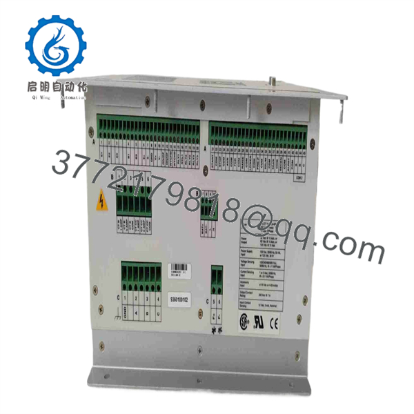
DECS-200-2C
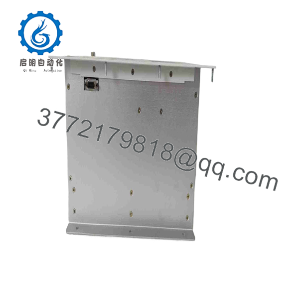
DECS-200-2C
Installation & Configuration Guide
Stage 1: Pre-Installation Preparation — Allow 10–15 Minutes
⚠️ Safety First: This is generator excitation equipment. Do not treat it like a conventional low-voltage PLC module. Notify operations, place the generator in a safe operating state, isolate the applicable excitation and control-power sources, apply lockout/tagout, and verify absence of hazardous voltage with an appropriately rated meter. Allow at least 5 minutes for discharge, then verify the actual circuit condition.
Tools Required
- ESD wrist strap and suitable ESD work surface.
- PH1/appropriate terminal screwdriver.
- Calibrated multimeter.
- Wire labels and marker.
- Smartphone or camera for configuration photographs.
- Laptop with the appropriate Basler BESTCOMS-DECS200 software and communication cable.
Data Backup
- Record the complete DECS-200 nameplate/style information.
- Photograph every terminal connection before removing anything.
- Record generator voltage, CT/PT ratios, field voltage, and field-current ratings.
- Record communication settings and Modbus parameters.
- Connect the existing unit to BESTCOMS where practical and save the configuration.
- Record alarm, limiter, stability, AVR, FCR, var, and power-factor settings.
The uses BESTCOMS software for configuration and provides a front-panel RS-232 connection for PC communication.
Stage 2: Removing the Old Unit — Allow 10 Minutes
The is a panel-mounted excitation controller, so the mechanical replacement procedure differs from a DIN-rail PLC module.
- Confirm all relevant power sources are isolated.
- Remove the enclosure or panel access cover as required.
- Photograph the terminal layout again before disturbing wiring.
- Label each conductor individually.
- Disconnect wiring without pulling on terminal blocks or conductor insulation.
- Remove the unit’s panel mounting hardware.
- Carefully withdraw the from the panel.
- Inspect the wiring, terminals, grounding connection, and surrounding panel area for heat damage, loose conductors, corrosion, or contamination.
⚠️ Keep the original available until commissioning is complete. Its configuration, terminal labeling, and nameplate information may be needed to resolve a replacement mismatch.
Stage 3: Installing the New Module — Allow 10–15 Minutes
- Verify the exact model and style information before applying power. A with a different power or excitation configuration is not automatically interchangeable.
- Wear the ESD strap before handling the electronics.
- Confirm the replacement’s control-power configuration matches the existing installation.
- Clone the documented configuration. Re-enter or restore the recorded settings rather than assuming factory defaults are suitable.
- Verify generator voltage sensing and current-transformer connections against the wiring diagram.
- Verify field positive and negative connections.
- Verify operating-power connections.
- Verify chassis ground.
- Verify RS-232/RS-485 communication wiring and Modbus parameters where used.
- Secure the controller using the appropriate panel hardware.
Self-Checklist
- Exact model/style verified
- Control-power rating verified
- Generator sensing wiring verified
- CT wiring verified
- Field wiring verified
- Operating-power wiring verified
- Ground connection secured
- Communication wiring verified
- Configuration backed up
- All terminal screws checked to the applicable Basler torque specification
⚠️ Do not rely on terminal position alone. The uses dedicated terminals for control power, operating power, generator sensing, field connections, and grounding. The manual identifies, for example, B7/B8 for DC control power, B9/B10 for AC control power on the applicable configuration, C1 for chassis ground, and C2–C4 for operating power.
Stage 4: Power-On & Testing — Allow 15–30 Minutes
- Perform a pre-power inspection.
- Check for accidental shorts.
- Verify polarity.
- Confirm no loose wire strands remain.
- Verify the cabinet ground.
- Apply control power according to the approved commissioning procedure.
- Observe the status indicators and front-panel behavior.
- Connect the commissioning laptop through the front RS-232 COM0 port.
- Open BESTCOMS-DECS200 and establish communication.
- Read the installed configuration before changing parameters.
- Compare generator sensing, field ratings, operating mode, limiters, stability settings, and communication parameters with the saved configuration.
- Verify RS-485 Modbus communication if the plant control system uses it.
- Perform the required dry-run and excitation-system checks according to the generator commissioning procedure.
- Restore the generator to service only after the excitation response and protection functions have been verified.
The COM0 interface uses a 9-pin RS-232 connector and supports 1,200–19,200 baud. COM2 uses RS-485 with Modbus and supports 1,200–19,200 baud.
⚠️ Troubleshooting Note: If BESTCOMS cannot communicate, check the physical serial connection, selected PC port, baud settings, and communication port first. If generator voltage does not respond correctly, stop the commissioning sequence and verify sensing polarity, PT/CT wiring, field configuration, and the programmed operating mode before making further adjustments.
Frequently Asked Questions (FAQ)
Q1. Is the Basler -2C obsolete?
Yes. Current aftermarket listings identify -2C as discontinued by the manufacturer. That makes exact-style verification particularly important when sourcing replacement equipment. Do not assume another variant is a direct electrical substitute without checking the complete style number and application.
Q2. Is the -2C the same as every model?
No. The family has different control-power and application configurations. The documentation distinguishes configurations such as the 24/48 Vdc option and the 120 Vac/125 Vdc option. The excitation output also has to match the generator field requirements. Verify the nameplate and style information before ordering.
Q3. Can I hot-swap the -2C?
Do not treat it as a hot-swappable PLC module. The has dedicated control-power, operating-power, generator-sensing, and field connections. Isolate the appropriate power sources and follow the generator/excitation system’s approved shutdown and LOTO procedure before removal. The exact plant procedure takes priority over a generic replacement sequence.
Q4. Will I lose the generator control settings when replacing the unit?
Potentially, yes. Do not assume the replacement contains the same application parameters. Before removing the old controller, save the BESTCOMS configuration where possible and photograph or document critical settings. Pay particular attention to AVR/FCR settings, limiters, stability parameters, sensing configuration, and communication settings.
Q5. What excitation output d support?
The platform supports 32 Vdc, 63 Vdc, and 125 Vdc nominal continuous field-voltage applications at up to 15 Adc. The published specifications also provide higher 10-second forcing levels and associated minimum field-resistance requirements. The correct output configuration must match the actual generator exciter field.
Q6. D support Modbus?
Yes. The provides an RS-485 COM2 interface using Modbus. The published communication range is 1,200–19,200 baud, 8N1, half duplex. It also provides two RS-232 interfaces: COM0 for local PC communication and COM1 for optional autotracking between units.
Q7. What condition should I specify when buying a replacement?
For a discontinued controller, specify the physical condition explicitly: Factory Sealed, New Original / New Surplus, or Refurbished (tested). Ask for photographs of the actual unit, nameplate/style number, serial number, packaging, and test documentation. If the supplier cannot identify the exact condition, do not treat the item as factory-new.
replacement work, I would also request a configuration compatibility check against the existing nameplate/style number before shipment. That is more useful than simply matching the base model number.



