
 WhatsApp: +86 16626708626
 Email:
  Phone: +86 16626708626
Description
Key Technical Specifications
| Parameter | Specification |
| Manufacturer | Bender GmbH & Co. KG |
| Model / Part Number | IRDH265-2 / B91065001 |
| Nominal System Voltage (Un) | 3AC, AC, AC/DC 0–793 V |
| Supply Voltage (Us) | AC 88–264 V / DC 77–286 V (42–460 Hz) |
| Measuring Principle | AMP-Plus (Adaptive Measuring Principle for high system capacities) |
| Response Value (R_{an}) | Adjustable Alarm 1 (R_{an1}): 1 kΩ–10 MΩ |
| Output Relays | 2 SPDT contact sets (Alarm 1 and Alarm 2) |
| Display & Diagnostics | LC Display with bar graph and numerical kΩ/MΩ resistance values |
| Communication / Interfaces | RS485 (BMS protocol) |
| Operating Temperature | −10°C to +55°C |
| Mounting Format | DIN Rail Mount / Panel Mount Base |
Product Introduction & Supply Chain Strategy
The Bender IRDH265-2 ISOMETER is an advanced insulation monitoring relay designed for ungrounded (IT) power distribution systems across healthcare facilities, marine vessels, paper mills, and industrial automation networks. Utilizing Bender’s patented AMP-Plus measurement technology, it accurately evaluates ground insulation resistance in modern electrical circuits containing variable frequency drives (VFDs), power electronics, and DC components without triggering false alarms from system leakage capacitance.
This product is a Brand New Surplus unit. It is not used, not pulled from a decommissioned plant, and not refurbished. All modules undergo rigorous quality verification to ensure OEM-level reliability.
Refurbished insulation monitors pose severe operational risks due to aged measuring capacitors, degraded internal current transformers, and drifting calibration values. An undetected ground fault in an IT power grid can result in catastrophic second-fault short circuits, unexpected equipment destruction, or sudden facility power failure. Sourcing genuine New Surplus inventory ensures factory-calibrated measurement precision, protects your baseline Total Cost of Ownership (TCO), and secures exact-fit replacements without necessitating panel re-engineering or electrical system re-certification.
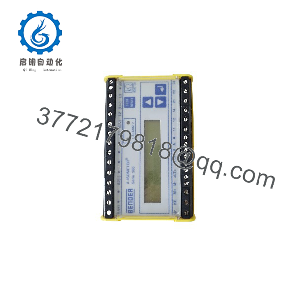
IRDH265-2
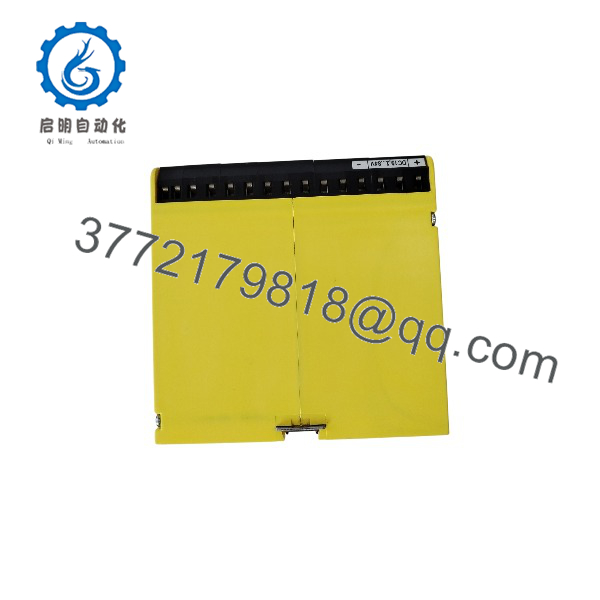
IRDH265-2
Installation & Configuration Guide
Stage 1: Pre-Installation (Prep & Safety)
- Perform Lock-Out/Tag-Out (LOTO) procedures on both the main system supply and the auxiliary control voltage feeds.
- Put on an anti-static wrist strap and follow standard ESD safety protocols.
- Record existing alarm threshold settings (R_{an1}, R_{an2}), analog output configuration, and BMS address switch settings from the old unit.
Stage 2: Removal
- Disconnect the terminal plug headers from the top and bottom of the IRDH265-2 module.
- Release the DIN-rail locking tab using a flat-head screwdriver.
- Gently lift the unit off the mounting rail and place it into ESD protective packaging.
Stage 3: Installation (Clone & Seat)
- Snap the replacement IRDH265-2 securely onto the DIN rail inside the enclosure.
- Reconnect terminal wiring harnesses, ensuring the measuring coupling connection (Terminals L1/L2) and ground reference bonds (Terminals E/KE) are firmly torqued.
- Power up the auxiliary supply (Us) only and navigate the front menu to configure alarm thresholds, relay operating modes (fail-safe vs. non-fail-safe), and memory settings to match original parameters.
Stage 4: Power-On & Testing
- Apply main system voltage (Un) to the monitored power circuit.
- Observe the LCD screen to confirm the system displays stable real-time insulation resistance values in MΩ.
- Press the front panel TEST button to simulate an internal ground fault condition; verify that both alarm LEDs illuminate and output relays trigger as configured.
Firmware/Software Versions & Upgrade Notes
- System Compatibility: Ensure the device software revision matches connected BMS bus networks or remote indicator panels (e.g., Bender MK2430 or TM Series interfaces).
- Backward Compatibility: The IRDH265-2 is physically and electrically backward compatible with older IRDH265 variants; however, verify menu parameter settings for analog signal scaling (0–20 mA vs. 4–20 mA).
- Firmware Risks: Do not interrupt auxiliary power during device parameter saves or system resets. Interrupted power writes can corrupt EEPROM settings, forcing the unit into a system error loop.
Frequently Asked Questions (FAQ)
Q: Is this Bender -2 unit brand new, or has it been reconditioned?
A: This module is 100% genuine New Surplus. It has zero field operating hours, pristine terminal connectors, unmarred housing latching tabs, and original factory calibration. It is not used, repaired, or refurbished.
Q: Why should I choose New Surplus over a cheaper refd ?
A: Refurbished insulation relays often suffer from drifted internal reference resistors and degraded internal power supplies. In ungrounded IT networks, a malfunctioning insulation monitor can fail to detect ground faults, leading to catastrophic phase-to-phase short circuits during a second fault event. New Surplus guarantees original OEM safety performance and full service life.
Q: Hoe tested prior to dispatch?
A: Every unit undergoes rigorous Quality Control bench testing. Technicians conduct visual package checks, verify auxiliary power-up self-tests, validate LCD screen output, and perform functional test/reset loop checks to confirm proper relay actuation.
Q: Is thr still actively produced by the manufacturer?
A: The series is a legacy insulation monitoring line. Sourcing New Surplus stock enables maintenance teams to maintain buffer stock and perform immediate direct replacements without redesigning panel layouts or upgrading entire monitoring systems.
Q: Does this module require external coupling devices for higher voltages?
A: For nominal AC system voltages up to 793 V and DC voltages up to 65e connects directly to the network. For higher system voltages, an external Bender coupling device (such as the AGH series) must be utilized.
Q: What warranty coverage applies to this unit?
A: This New Surplur includes a comprehensive 1-Year replacement warranty covering functional and electronic defects.



