
 WhatsApp: +86 16626708626
 Email:
  Phone: +86 16626708626
Description
3. Key Technical Specifications
- Model Number: 170180-02-05
- Manufacturer: Bently Nevada (GE)
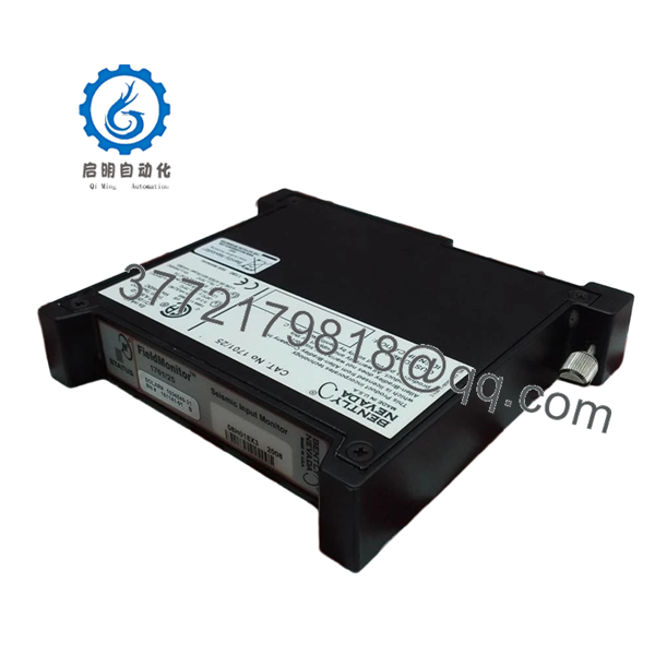
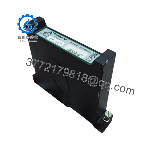
- Product Series: FieldMonitor™ External Transducer I/O Module
- Module Type: Dual Velocity Transducer I/O Module
- Channels: 2 channels
- Input Type: Two 2-wire velocity transducers
- Compatible Sensors: 9200, 74712 velocity sensors and equivalent types
- Mounting: One slot in FieldMonitor terminal base
- Input Voltage Range: 0 to −Vt
- Output Voltage Range: 0 to −Vt
- Frequency Response: −5% at >25 kHz
- Current Draw: 2.0 mA maximum (without transducer)
- Operating Temperature: −34 °C to +85 °C
- Storage Temperature: −40 °C to +85 °C
- Weight: Approximately 277 g (0.61 lb)
- Hazardous Area Rating: Division 2 / Zone 2 applications with approved configuration
4. Product Introduction
The Bently Nevada 170180-02-05 is a FieldMonitor External Transducer I/O Module designed to connect two-wire velocity transducers to Bently Nevada machinery monitoring systems. It provides signal interface functions for vibration monitoring applications in rotating equipment such as turbines, compressors, and industrial motors.
The module occupies one FieldMonitor terminal base slot and supports two independent velocity sensor inputs. Before replacement, verify the installed terminal base, sensor model, and monitoring module compatibility to avoid signal scaling or configuration issues.

- 170180-02-05
5. Installation & Configuration Guide
Stage 1: Pre-Installation Preparation (Approx. 10 minutes)
⚠️ Safety First
- Notify plant operations about the planned maintenance window.
- Confirm the rotating machine is in a safe shutdown condition.
- Apply lockout/tagout procedures.
- Isolate system power and wait at least 5 minutes before removing hardware.
Tools Required
- ESD wrist strap
- PH1 screwdriver
- Digital multimeter
- Wire labels
- Smartphone/camera for documentation
Data Backup
- Record the FieldMonitor terminal base slot location.
- Photograph all wiring before removal.
- Record connected velocity sensor models.
- Save existing monitoring configuration where applicable.
Stage 2: Removing the Old Module (Approx. 5 minutes)
- Remove the FieldMonitor enclosure cover if required.
- Label Channel A and Channel B wiring.
- Disconnect terminal wiring carefully.
- Release module retaining hardware.
- Pull the module straight out from the terminal base.
⚠️ Note: Keep the removed module until the replacement has passed signal verification.
Stage 3: Installing the New Module (Approx. 10 minutes)
- Wear an ESD strap before handling the replacement unit.
- Verify the part number matches 170180-02-05.
- Confirm the replacement module is installed in the same terminal base position.
Configuration Clone (Critical)
- Match:
- Channel A sensor wiring
- Channel B sensor wiring
- Sensor type
- Monitoring channel assignment
- Insert the module into the FieldMonitor terminal base.
- Ensure the module is fully seated.
- Tighten terminal connections using appropriate torque.
Self-Checklist
- Correct model verified
- Channel wiring matched
- Module seated correctly
- Terminal connections secure
Stage 4: Power-On & Testing (Approx. 15 minutes)
Pre-Power Check
- Check wiring continuity.
- Verify no short circuit exists on sensor wiring.
- Confirm terminal base power condition.
Power-On Steps
- Energize the FieldMonitor system.
- Verify module status indicators.
- Confirm monitoring system communication.
- Check velocity signal values.
- Compare readings against the previous module.
⚠️ Troubleshooting Note
- Incorrect vibration values: Check sensor polarity and wiring.
- No signal: Verify two-wire velocity transducer compatibility.
- Channel fault: Confirm the monitoring module configuration matches the installed I/O type.
6. Frequently Asked Questions (FAQ)
Q1: Can the Bently 170180-02-05 be hot-swapped while powered?
No. Unless the specific FieldMonitor installation documentation confirms live replacement, remove power before exchanging the module. Pulling I/O modules under power can create unexpected faults and may damage the terminal interface.
Q2: What sensors can the 170180-02-05 connect to?
The module is designed for two 2-wire velocity transducer inputs. Typical compatible sensors include Bently Nevada 9200 and 74712 velocity transducers. Always verify the exact sensor datasheet before replacement.
Q3: Is the Bently 170180-02-05 obsolete?
The FieldMonitor product family is an older installed system. Availability is mainly through industrial automation spare-part channels and surplus inventory. Confirm condition, serial traceability, and test records before installation.
Q4: What is the most common replacement mistake?
The common mistake is installing a physically compatible module with incorrect sensor wiring or channel configuration. I have seen maintenance teams replace the hardware correctly but spend hours troubleshooting because Channel A and Channel B assignments were reversed.
Q5: What inspection should be performed on a surplus 170180-02-05?
A proper inspection should include:
- Serial number verification
- External condition check
- Connector inspection
- Power-up verification
- Channel signal testing
- Documentation of test results
For critical machinery protection systems, avoid installing untested spare modules.
Q6: Why is this module cheaper than current OEM equipment?
Pricing usually reflects lifecycle status, availability, and sourcing channel. New surplus units may come from unused project inventory, while refurbished units have different inspection histories. Always confirm whether the supplied unit is New Original, New Surplus, or Refurbished (tested).
Q7: What should I check before ordering a replacement?
Verify:
- Full part number: 170180-02-05
- FieldMonitor terminal base compatibility
- Connected velocity transducer model
- Existing monitoring module type
- Required hazardous-area approval
A close-looking Bently module may have different sensor interfaces and cannot always be substituted directly.


