
 WhatsApp: +86 16626708626
 Email:
  Phone: +86 16626708626
Description
Key Technical Specifications
| Parameter | Value |
|---|---|
| Manufacturer | Bently Nevada (Baker Hughes) |
| Model | 128240-01 |
| Product Type | Prox/Seismic I/O Module |
| Compatible Monitor | 3500/42M Proximitor/Seismic Monitor |
| Installation Position | Rear I/O slot of 3500 rack |
| Termination Type | External Terminations |
| Supported Sensors | Proximitor®, Seismoprobe®, Prox/Accel, Velomitor® (application dependent) |
| Rack Requirement | One full-height rear slot |
| Application | Machinery protection and condition monitoring |
| System | Bently Nevada 3500 Series |
| Country of Origin | USA (typical) |
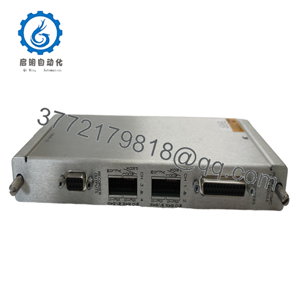
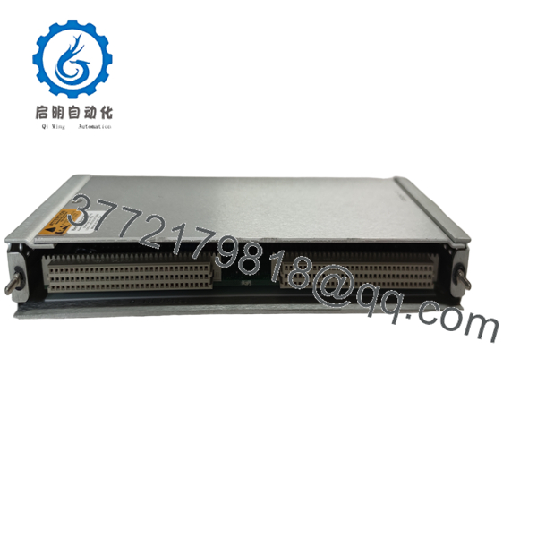
The 128240-01 is the external termination I/O module option for the 3500/42M Proximitor/Seismic Monitor. It connects field transducers to the monitor and is intended for installations where external terminal blocks simplify field wiring and maintenance.
Product Introduction
The Bently Nevada 128240-01 is a rear-mounted Prox/Seismic I/O Module designed for use with the 3500/42M Proximitor/Seismic Monitor. Rather than performing signal processing itself, it serves as the electrical interface between field-mounted vibration sensors and the monitor installed in the 3500 Machinery Protection System.
Its external termination design allows field wiring to terminate outside the monitor module, reducing maintenance time during replacement and minimizing the risk of disturbing existing plant wiring. The module supports proximity probes and seismic transducers used for vibration, shaft position, and machine condition monitoring in turbines, compressors, pumps, and other rotating equipment.

- 128240-01
- 128240-01
Installation & Configuration Guide
Stage 1 – Pre-Installation Preparation (10 minutes)
⚠️ Safety First
- Notify operations before shutting down the monitoring system.
- Perform Lock-Out/Tag-Out procedures.
- Remove power from the 3500 rack.
- Wear a grounded ESD wrist strap.
- Save the current 3500 rack configuration.
- Label every field cable connected to the external termination block.
- Photograph all wiring before removal.
Stage 2 – Remove the Existing I/O Module (5–10 minutes)
- Disconnect the external terminal wiring.
- Remove the monitor if required to access the rear I/O module.
- Release the mounting hardware.
- Remove the I/O module straight out of the rack.
- Inspect connectors for bent pins or contamination.
⚠️ Do not force the connector. Bent backplane pins are far more expensive to repair than replacing an I/O module.
Stage 3 – Install the Replacement Module (10 minutes)
- Verify the replacement part number is 128240-01.
- Confirm it matches the required external termination configuration.
- Install the module into the correct rear slot.
- Reinstall the monitor.
- Reconnect all field wiring according to the wiring diagram.
- Verify terminal torque before energizing the rack.
Installation Checklist
- ✓ Correct part number
- ✓ Correct monitor (3500/42M)
- ✓ External wiring verified
- ✓ Rear connector fully seated
- ✓ Rack configuration available
Stage 4 – Power-Up & Functional Testing (15 minutes)
- Restore rack power.
- Verify the monitor completes its self-test.
- Check that all connected sensors are recognized.
- Confirm acceptable transducer bias voltages.
- Verify vibration and position measurements.
- Test alarm and relay functions.
⚠️ Troubleshooting Tip
Most startup problems after replacing a 128240-01 are caused by:
- Installing an internal-termination I/O module instead of the external version.
- Wiring landed on incorrect terminal positions.
- Loose external terminal screws.
- Sensor type configured incorrectly in the 3500 Rack Configuration Software.
I’ve seen technicians spend hours troubleshooting a “failed” monitor that turned out to have the wrong I/O module installed. Always verify the rear module option before powering the rack.
Frequently Asked Questions (FAQ)
Q1. What is the 128240-01 used for?
It is the external termination Prox/Seismic I/O Module used with the Bently Nevada 3500/42M Proximitor/Seismic Monitor. It provides the interface between field sensors and the monitoring system.
Q2. Can this module operate by itself?
No. The 128240-01 is a rear I/O module and must be installed with a compatible 3500/42M monitor in a Bently Nevada 3500 rack.
Q3. What is the difference between 128240-01 and 128229-01?
The primary difference is the termination method:
- 128240-01 — External terminations
- 128229-01 — Internal terminations
Choose the version that matches your existing rack wiring. Mixing the two usually requires rewiring the cabinet.
Q4. Which sensors are supported?
Depending on the monitor configuration, the module supports:
- Proximitor® probes
- Seismoprobe® transducers
- Prox/Accel sensors
- Velomitor® sensors (supported for some configurations)
Q5. Can I hot-swap the I/O module?
No. De-energize the 3500 rack before replacing the rear I/O module. Hot swapping can interrupt machinery protection and may damage the backplane connection.
Q6. What should I verify before ordering?
Confirm:
- Part number: 128240-01
- Compatible monitor: 3500/42M
- External termination requirement
- Sensor type
- Rack slot location
- Existing wiring configuration
Verifying these items before installation significantly reduces commissioning time and avoids unnecessary rewiring.



