
 WhatsApp: +86 16626708626
 Email:
  Phone: +86 16626708626
Description
3. Key Technical Specifications
| Parameter | Value |
|---|---|
| Product Type | 16-Channel Relay Module |
| Part Number | 135462-01 |
| Series | Bently Nevada 3500 Machinery Protection System |
| Relay Channels | 16 independent relay outputs |
| Relay Type | Dry-contact configurable outputs |
| Logic Functions | AND, OR, Voting, Latching, Non-latching |
| Installation | Front module with dedicated rear I/O module |
| Power Source | Supplied through 3500 rack backplane |
| Communication | Configured through 3500 Configuration Software |
| Operating Temperature | -30 °C to +65 °C |
| Mounting | Standard 3500 Rack |
| Typical Applications | Alarm annunciation, ESD interface, PLC interlocks, turbine trips |
Compatibility Note: The 135462-01 relay module is intended for the Bently Nevada 3500 Machinery Protection System. Verify the matching rear I/O module and rack configuration before replacement, as relay terminal arrangements depend on the installed I/O option.
4. Product Introduction
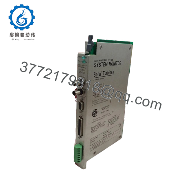
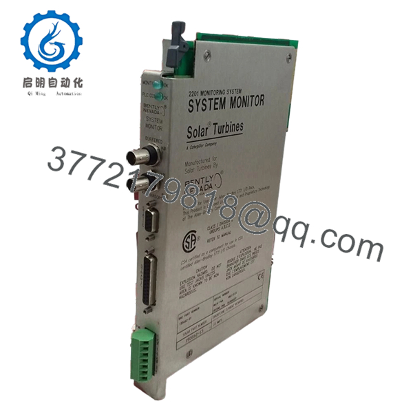
The Bently Nevada 135462-01 is a 16-Channel Relay Module for the 3500 Machinery Protection System. It converts alarm and protection events generated by monitor modules into hardwired relay outputs for connection to PLCs, emergency shutdown (ESD) systems, turbine control systems, annunciators, and other plant protection equipment.
Each relay channel can be configured independently using the 3500 Configuration Software. The module supports programmable relay logic, including voting, latching, and fail-safe operation, making it suitable for critical rotating equipment such as turbines, compressors, generators, and large pumps.

- 135462-01
- 135462-01
5. Installation & Configuration Guide
Stage 1 — Pre-Installation Preparation (10 Minutes)
⚠️ Safety First
- Notify operations of the planned maintenance window.
- Verify all protected equipment is in a safe operating condition.
- Apply Lock-Out/Tag-Out (LOTO) procedures.
- Remove power from the 3500 rack.
- Wait at least 5 minutes before removing modules.
Tools Required
- Grounded ESD wrist strap
- PH1 screwdriver
- Fluke 115 digital multimeter
- Wire identification labels
- Smartphone for wiring documentation
- Laptop with 3500 Configuration Software
Data Backup
- Export the complete rack configuration.
- Record relay assignments.
- Save alarm and trip logic.
- Photograph every relay terminal connection.
- Record firmware revision of the rack.
Stage 2 — Removing the Existing Module (5 Minutes)
- Remove the rack front cover.
- Label all field wiring before disconnecting.
- Disconnect the rear relay wiring carefully.
- Release the retaining mechanism.
- Pull the module straight out without twisting.
Inspect for:
- Bent backplane connectors
- Loose terminals
- Corrosion
- Dust accumulation
⚠️ Keep the original relay module until every relay output has been verified during commissioning.
Stage 3 — Installing the New Module (10 Minutes)
- Wear a grounded ESD wrist strap.
- Verify the replacement is 135462-01.
- Confirm the matching rear I/O module is installed.
- Insert the relay module until fully seated.
- Lock the retaining mechanism.
- Restore all wiring according to the documented terminal layout.
Self-Checklist
- ☑ Part number verified
- ☑ Rear I/O module matched
- ☑ Wiring restored
- ☑ Module fully seated
- ☑ Locking tabs secured
Stage 4 — Power-On & Functional Testing (15 Minutes)
Pre-Power Checks
- Measure rack supply voltage.
- Verify there are no shorts across relay wiring.
- Confirm all terminal screws are tightened.
Startup Procedure
- Energize the 3500 rack.
- Observe normal LED startup.
- Connect using 3500 Configuration Software.
- Verify the relay module is recognized.
- Confirm relay assignments.
- Simulate alarm conditions.
- Verify each relay energizes correctly.
- Confirm operation of connected PLC or ESD inputs.
- Review the event log for diagnostic faults.
⚠️ Troubleshooting Notes
Relay Does Not Operate
- Incorrect relay assignment
- Wiring error
- Configuration not downloaded
- Faulty external power circuit
Unexpected Relay Activation
- Incorrect voting logic
- Incorrect fail-safe configuration
- Alarm setpoints configured improperly
No Communication
- Module not fully seated
- Rack configuration mismatch
- Backplane connector issue
Engineer’s Installation Notes
One of the most common commissioning issues isn’t a failed relay module—it’s undocumented relay mapping. During shutdowns, technicians often disconnect dozens of alarm circuits at once. If every terminal isn’t labeled before removal, reconnecting the system can consume far more time than replacing the module itself.
Another point worth checking is the relay philosophy. Many plants configure trip relays as normally energized for fail-safe operation, while others use normally de-energized outputs. Installing a replacement without verifying the original configuration can trigger nuisance trips or prevent shutdown signals from operating as intended. I’ve seen entire startup schedules delayed because one relay was configured with the wrong fail-safe logic.
6. Frequently Asked Questions (FAQ)
Q1. What is the primary function of the 135462-01?
The 135462-01 provides 16 programmable relay outputs for machinery protection systems. It converts alarms and trip conditions from 3500 monitor modules into hardwired outputs for PLCs, DCSs, ESD systems, and annunciators.
Q2. Can each relay be configured independently?
Yes. Each relay channel can be assigned to different alarm sources and configured with latching, non-latching, voting, AND/OR logic, or fail-safe behavior using the 3500 Configuration Software.
Q3. Does this module provide measurement functions?
No. The 135462-01 does not monitor vibration or process variables directly. It acts as an output interface, responding to alarms generated by other 3500 monitor modules.
Q4. Is the 135462-01 still available?
Although the 3500 platform remains widely used in power generation, oil and gas, and petrochemical facilities, many relay modules are now supplied through new-surplus inventory or qualified industrial automation distributors. Availability depends on current stock levels.
Q5. Can I hot-swap the relay module?
While some 3500 modules support online replacement, replacing a relay module that controls trip circuits should normally be performed during a planned outage. Disconnecting relay outputs during operation may temporarily disable machinery protection or ESD functions.
Q6. What quality inspections should a supplier perform before shipment?
A qualified supplier should complete:
- OEM serial number verification
- Anti-counterfeit inspection
- Visual inspection for corrosion, scratches, and repair marks
- Functional testing in a genuine 3500 rack
- Verification of all 16 relay outputs
- Continuous operational burn-in (24 hours recommended)
- Insulation resistance testing (>10 MΩ)
- Firmware and hardware revision documentation
- ESD-safe packaging with QC sign-off
Test reports, relay operation videos, and inspection photographs should be available upon request. These records provide confidence that the module has been verified under operating conditions before shipment.



