
 WhatsApp: +86 16626708626
 Email:
  Phone: +86 16626708626
Description
3. Key Technical Specifications
| Parameter | Value |
| Module Type | Full-slot Display Interface Module (DIM) |
| System Compatibility | Bently Nevada 3500 series racks |
| Power Consumption | 15.5 watts maximum (Combined DIM and Display Unit) |
| Communication Protocol | Proprietary internal network to RS422 external interface |
| Compliance Standards | API Standard 670 (Machinery Protection Systems) |
| Distance Support (Standard) | Up to 30 meters (100 feet) from the 3500 system rack |
| Distance Support (Extended) | Up to 1,220 meters (4,000 feet) with external power supply |
| Dimensions | 2.5 cm x 25.5 cm x 24.0 cm (Standard 3500 slot card form factor) |
| Weight | 0.8 kg (1.76 lbs) |
4. Product Introduction & Supply Chain Strategy
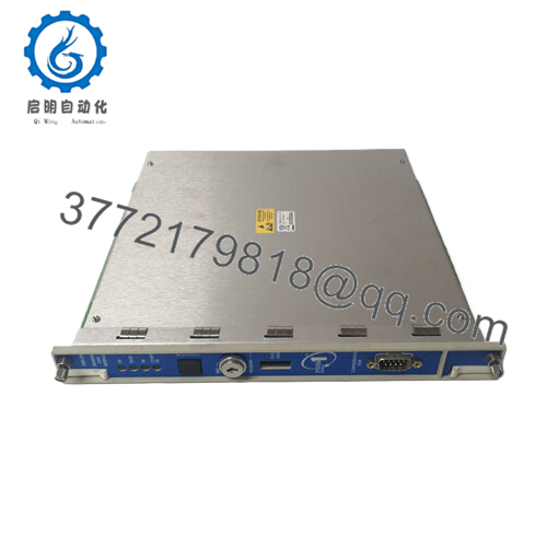
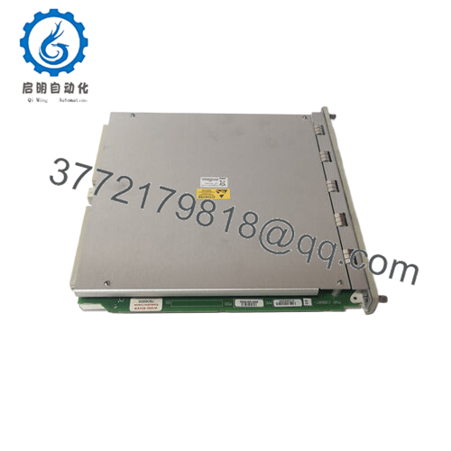
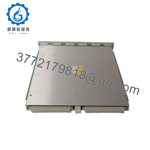
The Bently Nevada 135799-01 is the internal Display Interface Module (DIM) Printed Wire Assembly (PWA) designed for the 3500/93 System Display layout. It operates within the standard 3500 machinery protection rack, aggregating critical operating metrics, alarm event lists, system event logs, and status diagnostics from all neighboring I/O, relay, and Keyphasor modules. It then drives this data directly to the physical user-interface screen, fulfilling API 670 requirements for local operator visibility at the machinery skid.
From an inventory and asset lifecycle management perspective, the 135799-01 is a critical infrastructure anchor. If a DIM card fails, control room automation continues to monitor vibration, but local operators lose immediate, real-time diagnostic visibility at the asset itself. Securing this part as New Surplus guarantees zero previous thermal or component stress on the communications processors. This strategy ensures long-term operational availability and avoids the clear reliability hazards associated with refurbished components, which often fail under the ambient vibration and heat found near turbine enclosures.

- 135799-01
5. Installation & Configuration Guide
Stage 1: Pre-Installation (Prep & Safety)
- Put on a properly grounded static-dissipative wrist strap before sliding the card out of its protective anti-static shield. Static discharge can destroy the surface-mount logic arrays on the board.
- Identify the target slot position. Note that if you are using a Face-Mounted display option, the 135799-01 DIM must be placed specifically into Slot 15 (the right-most slot) of a full-size 3500 rack.
- Confirm that the rack configuration profiles are backed up within the 3500 Rack Configuration Software before beginning hardware maintenance.
Stage 2: Removal
- If replacing an existing module, unfasten the two hardware retaining screws located at the top and bottom edges of the card face.
- Fold out the integrated ejector tabs to release the board pins from the backplane assembly.
- Slide the old card out smoothly along the chassis guide rails, making sure not to contact components on adjacent slots.
Stage 3: Installation (Clone & Seat)
- Check that the physical configuration jumpers and DIP switch blocks on the new 135799-01 mirror the settings of the module you removed.
- Align the card edges with the upper and lower slot guide rails inside the rack housing.
- Slide the module firmly backward into the chassis until the rear pin socket engages completely with the backplane connections, then press the ejector handles flat.
- Hand-tighten the upper and lower retaining screws to lock the card mechanically into place.
Stage 4: Power-On & Testing
- Reapply power to the slot or rack system. Monitor the localized status LEDs on the module front plate during boot initialization.
- The green “OK” LED must light up solid, indicating the card has passed its internal power-on self-test (POST) routine.
- Connect the display cable to the DIM interface port, and verify that the 3500/93 screen successfully completes its communication handshake and populates live data channels.
6. Firmware/Software Versions & Upgrade Notes
The 135799-01 DIM operates as an integrated piece of the broader 3500 architecture. To maintain proper system behavior during a hardware swap, you must ensure system firmware compatibility:
- Firmware Baseline: The 135799-01 requires a minimum of revision G or later running on the 3500/20 Rack Interface Module (RIM) to establish proper internal data bus routing.
- Software Prerequisites: To configure or map custom screens for the display loop connected to this module, your engineering workstation must run 3500 Configuration Software version 2.41 or later, alongside 3500 Operator Display Software version 1.20 or later.
- Mismatch Risks: Swapping a DIM without matching firmware baselines can induce internal communications bus timeouts, causing the main rack to log a system error and drop local screen communication entirely.
7. Frequently Asked Questions (FAQ)
What is the exact difference between a 3500/93 module and this 135799-01 part?
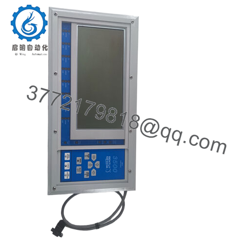
The designation 3500/93 refers to the complete Bently Nevada System Display catalog configuration, which typically includes both the external display screen and the internal interface components. The 135799-01 is the specific internal Display Interface Module (DIM) card that mounts directly into the 3500 rack backplane to drive that system display.
Can this module be installed in a 3500 Mini-rack system?
If you plan to utilize the Face-Mount style display option, it is not compatible with the 3500 Mini-rack configuration. Face-mounting requires the card to reside exclusively in Slot 15 of a full-size rack. Independent or standard panel-mount display configurations, however, can connect to the card via standard routing options.
Why choose a New Surplus 135799-01 over a cheaper refurbished alternative?
Refurbished display modules are often sourced from older, decommissioned plants and may look functional on the surface, but their communication processors, capacitor arrays, and line drivers have already weathered years of industrial heat and voltage variations. Buying a verified New Surplus unit ensures you get clean hardware with zero operational degradation. This eliminates the risk of premature component failure that can leave operators blind during a machinery validation process.
Is it possible to connect two distinct display units to a single 135799-01 module?
No. Each individual 3500/93 display unit requires its own dedicated 135799-01 Display Interface Module card. A full-size 3500 rack layout supports a maximum of two independent displays, meaning you must install two separate DIM cards into the rack backplane to support them.
What happens to the underlying machinery protection if this module fails?
Machinery protection functions independently of this card. If the 135799-01 suffers an unexpected failure, the primary monitoring boards (such as the 3500/42M or 3500/45) continue to read transducer signals and execute trip relays normally. The failure simply stops data transmission to the local display screen, temporarily blinding local maintenance teams at the machine skid.



