
 WhatsApp: +86 16626708626
 Email:
  Phone: +86 16626708626
Description
Key Technical Specifications
| Parameter | Value |
|---|---|
| Manufacturer | Bently Nevada |
| Part Number | 146031-01 |
| Product Family | 3500 Machinery Protection System |
| Associated System | 3500/22M Transient Data Interface |
| Product Type | 10Base-T/100Base-TX I/O Module |
| Ethernet Interface | 10Base-T / 100Base-TX |
| Physical Network Connection | RJ45 |
| Network Standard | IEEE 802.3 |
| Communication Protocol | BN Host Protocol / BN TDI Protocol |
| System Connection | 3500/22M TDI |
| Data Function | Static and transient machinery data transfer |
| Typical Power Consumption | 10.5 W |
| Maximum Current | 0.5 A |
| Supply Voltage | 24 VDC |
| Operating Temperature | -30 to +65 °C |
| Storage Temperature | -40 to +85 °C |
| Humidity | 95%, non-condensing |
| Approx. Dimensions | 241.3 × 24.4 × 99.1 mm |
| Approx. Weight | 0.4 kg |
| Ethernet Media | Shielded Category 5 copper Ethernet |
The current 3500/22M datasheet specifically lists 146031-01 as the 10Base-T/100Base-TX copper Ethernet I/O module and distinguishes it from 146031-02, which is the 100Base-FX fiber-optic version, and 146031-03, a GLD-plated 10Base-T/100Base-TX version.
Product Introduction
The Bently Nevada 146031-01 is the 10Base-T/100Base-TX Ethernet I/O module used with the 3500/22M Transient Data Interface. It provides the network connection between the 3500 monitoring rack and Bently Nevada host and machinery-management software. The module works with the 3500/22M TDI architecture alongside M-Series monitoring modules.
This part should be ordered as the Ethernet I/O module only, unless the application specifically requires a complete TDI assembly. The complete 3500/22 configuration can include the 288055-01 Standard TDI module together with 146031-01.
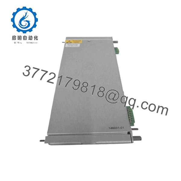
146031-01
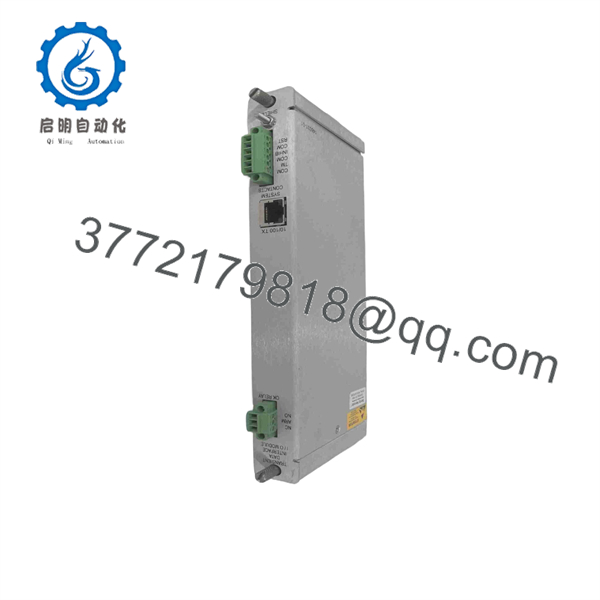
146031-01
Installation & Configuration Guide
Stage 1: Pre-Installation Preparation
Estimated time: 5–8 minutes
⚠️ Safety First: Place the machinery monitoring system in the approved maintenance state and follow the site’s electrical isolation and LOTO procedures before removing the module.
Tools Required
- ESD wrist strap
- Appropriate screwdriver
- Digital multimeter
- Wire labels
- Smartphone or camera
- Approved 3500/22M documentation
Data Backup
- Record the existing 3500/22M configuration.
- Photograph the complete TDI assembly.
- Record the installed I/O part number.
- Photograph the Ethernet cable and connector arrangement.
- Record the existing network configuration.
- Document the host/System 1 communication path.
- Verify whether the installed TDI is the standard 288055-01 + 146031-01 configuration.
⚠️ Do not order by “3500/22M Ethernet module” alone. The 3500/22M family has copper Ethernet, fiber Ethernet, and GLD-plated variants. The exact suffix determines the interface hardware.
Stage 2: Removing the Old Module
Estimated time: 5 minutes
- Place the rack in the approved maintenance condition.
- Verify that the installed I/O module is marked 146031-01.
- Label the Ethernet connection.
- Photograph the connector and cable routing.
- Disconnect the RJ45 Ethernet cable carefully.
- Release the applicable module retention hardware.
- Remove the I/O module straight from its mating interface.
- Inspect the connector and rack interface for bent contacts, contamination, or mechanical damage.
⚠️ Keep the old module available until the new module has established normal communications.
Stage 3: Installing the New Module
Estimated time: 5–8 minutes
- Verify the replacement part number: 146031-01.
- Confirm that the system uses the 10Base-T/100Base-TX copper Ethernet interface.
- Compare the replacement module’s physical connector arrangement with the removed unit.
- Install the I/O module into the 3500/22M assembly.
- Ensure the module is completely seated.
- Secure the applicable retaining hardware.
- Reconnect the RJ45 Ethernet cable.
- Verify that the cable is the correct shielded Ethernet type for the installation.
- Check that the cable is not under excessive mechanical tension.
Self-Checklist
- 146031-01 verified
- Copper Ethernet interface confirmed
- RJ45 connection secure
- Module fully seated
- Retaining hardware secured
- Ethernet cable inspected
- Network configuration documented
Stage 4: Power-On & Testing
Estimated time: 10–15 minutes
- Inspect the installation before applying power.
- Restore rack power using the site’s approved startup procedure.
- Verify normal 3500/22M status.
- Connect the Ethernet network.
- Verify the expected network link.
- Connect the engineering workstation or host system.
- Confirm communication with the 3500/22M.
- Verify BN Host communication.
- Confirm that the host can retrieve current 3500 rack data.
- If transient-data functionality is enabled, verify that the expected data is available to the host software.
- Record the replacement part number and test results.
The 3500/22M TDI provides static data capture as standard; dynamic/high-resolution transient data requires the appropriate Channel Enabling Disk configuration. Replacing 146031-01 alone does not create transient-data capability if the TDI configuration does not already have it.
⚠️ If the module powers up but the host cannot communicate, check the Ethernet physical layer first: cable, switch port, link status, network addressing, and the host-side configuration.
Frequently Asked Questions (FAQ)
1. What is Bently Nevada 146031-01?
146031-01 is the 10Base-T/100Base-TX Ethernet I/O module for the Bently Nevada 3500/22M Transient Data Interface. It provides the copper Ethernet interface used to connect the TDI to the applicable host and machinery-management software.
2. Is 146031-01 the complete 3500/22M Transient Data Interface?
No. This is one of the most important ordering distinctions. 146031-01 is the I/O/network module. A standard 3500/22 configuration can pair it with the 288055-01 Standard Transient Data Interface Module.
3. What is the difference between 146031-01 and 146031-02?
The interface is different. 146031-01 uses 10Base-T/100Base-TX copper Ethernet, while 146031-02 uses 100Base-FX fiber optic Ethernet. Do not substitute one for the other simply because both belong to the 3500/22M family.
4. Can 146031-01 be used with a 3500/22M system?
Yes, when the system is configured for the corresponding 10Base-T/100Base-TX Ethernet I/O option. The exact TDI ordering configuration, rack interface, and agency approval option still need to match the installation.
5. Will replacing 146031-01 erase the 3500/22M configuration?
The I/O module is not the same thing as the complete TDI configuration. Still, record the existing network and TDI settings before replacement. After installation, verify host communications and data acquisition rather than assuming that a physical replacement alone confirms correct operation.
6. Is 146031-01 interchangeable with 146031-03?
Not automatically. Both provide 10Base-T/100Base-TX functionality, but 146031-03 is the GLD-plated version. For installations with specific environmental, corrosion, or approval requirements, verify that the replacement’s construction matches the original specification. The OEM spare-parts table lists the two as separate part numbers.
7. What should I verify before ordering 146031-01?
Provide the supplier with the complete 146031-01 part number, a photograph of the existing module label, the installed 3500/22M configuration, and whether you need the I/O module only or the complete TDI assembly. Also confirm the copper Ethernet requirement. Current listings identify 146031-01 as a 10Base-T/100Base-TX module, while 146031-02 is fiber and 146031-03 is the GLD-plated variant.



