
 WhatsApp: +86 16626708626
 Email:
  Phone: +86 16626708626
Description
3. Key Technical Specifications
| Parameter | Value |
|---|---|
| Manufacturer | Bently Nevada |
| Model Number | 177230-01-01-05 |
| Product Type | Seismic Transmitter |
| Measurement Range | 0–25.4 mm/s (0–1.0 in/s) |
| Frequency Response | 10 Hz to 1 kHz RMS |
| Output Signal | 4–20 mA |
| Power Supply | 12–30 V DC |
| Temperature Range | −40 °C to +85 °C |
| Approval Options | CSA/NRTL/C, ATEX/IECEx |
| Mounting | 1/2-20 UNF threaded connection |
| Typical Application | Bearing housing and machine casing vibration monitoring |
| Integration | PLC, DCS, SCADA condition monitoring systems |
| Weight | Approx. 0.5 kg |
Specifications are based on available Bently Nevada 177230-01-01-05 product references. Confirm exact certification requirements and mechanical mounting details against the OEM datasheet before installation.
4. Product Introduction
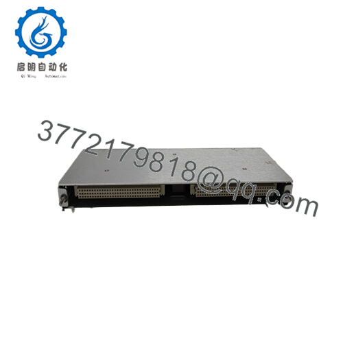
The Bently Nevada 177230-01-01-05 is a 177230 Series seismic transmitter used for industrial machinery vibration monitoring. It measures casing vibration velocity on rotating equipment such as motors, pumps, compressors, and turbines, then converts the signal into a 4–20 mA output for PLC, DCS, or SCADA systems.
The unit is designed for condition monitoring applications where continuous vibration data is required without a separate rack-mounted monitor. Its loop-powered design simplifies field installation and integration into existing plant monitoring systems.

- 177230-01-01-05
5. Installation & Configuration Guide
Stage 1: Pre-Installation Preparation (Approx. 10 minutes)
⚠️ Safety First
- Notify operations before maintenance work.
- Place the monitored machine into an approved maintenance condition.
- Apply lockout/tagout procedures if required.
- Verify the loop power is isolated before disconnecting wiring.
Tools Required
- ESD wrist strap
- Digital multimeter
- Adjustable wrench
- Wire labels
- Smartphone/camera for wiring documentation
Data Backup
- Record existing transmitter location.
- Photograph:
- Cable routing
- Terminal connections
- Existing transmitter mounting orientation
- Record PLC/DCS input channel scaling:
- 4 mA value
- 20 mA value
- Engineering units
Stage 2: Removing the Old Transmitter (Approx. 10 minutes)
- Isolate the 12–30 V DC loop supply.
- Label signal wires before removal.
- Disconnect the loop wiring carefully.
- Remove the transmitter from the mounting point.
- Inspect:
- Mounting threads
- Cable condition
- Connector sealing
- Machine mounting surface
⚠️ Note: Keep the old transmitter until the replacement signal has been verified.
Stage 3: Installing the New Module (Approx. 10 minutes)
- Verify the replacement model:
Old: 177230-01-01-05
New: 177230-01-01-05
- Confirm measurement range matches the existing application.
- Install the transmitter on the machine mounting point.
- Tighten using appropriate mechanical practice.
- Connect the 4–20 mA loop wiring.
Self-Checklist
- Correct model verified
- Mechanical mounting secure
- Loop polarity checked
- Cable routing protected
Stage 4: Power-On & Testing (Approx. 15–30 minutes)
Pre-Power Check
- Verify loop wiring polarity.
- Measure supply voltage.
- Confirm PLC/DCS analog input configuration.
Power-On Steps
- Apply loop power.
- Verify PLC/DCS receives a valid current signal.
- Check zero vibration baseline.
- Apply controlled machine operation.
- Confirm vibration value scaling.
⚠️ Troubleshooting Note
If the signal remains near 4 mA:
- Check sensor mounting.
- Verify loop power.
- Confirm input scaling.
If the signal is unstable:
- Inspect cable shielding.
- Check grounding.
- Verify mechanical mounting condition.
6. Frequently Asked Questions (FAQ)
Q1: What does the Bently Nevada 177230-01-01-05 measure?
It measures machine casing vibration velocity and outputs a proportional 4–20 mA signal for plant monitoring systems. It is commonly used for rotating equipment condition monitoring.
Q2: Can the 177230-01-01-05 connect directly to a PLC?
Yes. The transmitter provides a standard 4–20 mA output, allowing direct connection to compatible PLC, DCS, or SCADA analog input channels.
Q3: Is the 177230-01-01-05 obsolete?
No specific discontinuation notice was identified from the available references. However, industrial vibration transmitters should still be verified for current availability and replacement planning before critical equipment shutdowns.
Q4: What is the difference between 177230-01-01-05 and other 177230 variants?
The suffix defines configuration details such as measurement range, frequency response, and approval options. The -01-01-05 version specifies the 0–25.4 mm/s range, 10 Hz–1 kHz response, and approval configuration.
Q5: Does replacing this transmitter require software configuration?
Usually only PLC/DCS scaling verification is required. The transmitter itself is typically a fixed-output loop device. Confirm the existing analog input range before commissioning.
Q6: What condition should I request when purchasing?
For critical machinery monitoring, request:
- New Original / Factory New
- Serial number verification
- Functional test record
- Warranty documentation
Avoid purchasing units with unknown calibration history for protection-critical applications.
Q7: What should be checked before installing a replacement?
Verify:
- Part number: 177230-01-01-05
- Measurement range
- Frequency response
- Hazardous area approval requirements
- PLC/DCS input scaling
- Mechanical mounting compatibility


