
 WhatsApp: +86 16626708626
 Email:
  Phone: +86 16626708626
Description
Key Technical Specifications
| Parameter | Value |
|---|---|
| Model Number | 330180-50-00 |
| Manufacturer | Bently Nevada, a Baker Hughes business |
| Product Series | 3300 XL 8 mm Proximity Transducer System |
| Product Type | Proximitor Sensor / eddy-current proximity signal conditioner |
| Total System Length | 5.0 m / 16.4 ft combined probe and extension-cable electrical length |
| System Length Code | 50 |
| Mounting Option | Panel mount |
| Mounting Code | 00 |
| Agency Approval Option | No agency approvals specified |
| Approval Code | 00 |
| Compatible Probe System | Bently Nevada 3300 XL 8 mm probe and matched extension cable |
| Nominal Sensitivity | 200 mV/mil / 7.87 V/mm |
| Output Function | Linear DC gap/position signal with dynamic vibration component |
| Measurement Principle | Non-contact eddy-current displacement measurement |
| Primary Measurements | Shaft radial vibration and static shaft position / gap |
| Nominal Supply Range | −17.5 to −26 V DC |
| Nominal Operating Supply | −24 V DC |
| Typical Current Draw | Approximately 120 mA at −24 V DC |
| Dynamic Frequency Range | DC to 10 kHz, depending on the complete transducer system and connected monitor |
| Minimum Output Load | 10 kΩ resistive load |
| Standard Target Calibration | AISI 4140 steel target material; verify when monitoring nonstandard shaft materials |
| Typical Applications | Fluid-film-bearing turbines, compressors, pumps, motors, generators, Keyphasor reference, and speed measurement |
| Compatibility Warning | Requires an exactly matched 5.0 m probe-plus-extension-cable system; do not mix total-length options |
| Hazardous-Area Warning | The -00 approval suffix indicates no agency-approval option; verify area classification before installation |
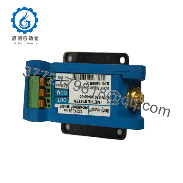
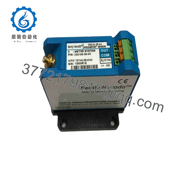
The Bently Nevada 330180-50-00 is a 3300 XL Proximitor Sensor configured for a 5.0 m total transducer-system length. The order code identifies panel mounting and no agency approvals. The official 3300 XL documentation identifies the Proximitor Sensor as part of a three-piece system consisting of a probe, extension cable, and sensor.
Product Introduction
The Bently Nevada 330180-50-00 is a panel-mount 3300 XL 8 mm Proximitor Sensor used in non-contact shaft-vibration and shaft-position measurement systems. It powers and conditions the eddy-current probe signal, then produces a linear output used by Bently Nevada monitors, machinery-protection racks, or compatible external monitoring equipment.
The 50 suffix is critical: this sensor is calibrated for a total 5.0 m probe-plus-extension-cable electrical path. The two 00 suffixes identify panel mounting and no agency-approval option. It must be paired with the correct 3300 XL 8 mm probe and extension cable; a mismatched cable length can shift gap voltage, vibration scaling, and alarm response.
330180-50-00
330180-50-00
Troubleshooting Quick Reference
| Symptom | Possible Cause | Relevance to This Part | Quick Check Method | Recommendation |
|---|---|---|---|---|
| No output signal from the Proximitor | Missing negative DC supply, open power return, damaged sensor, loose terminal, failed monitor input | ✅ High | Measure the supply directly at the sensor terminals. Confirm the required negative DC supply is present and stable, then inspect the output connection to the monitor. | Verify supply, return, fuse, and terminal torque before replacing the 330180-50-00. |
| Gap voltage is outside the expected range | Incorrect probe gap, wrong cable length, incompatible probe/cable, damaged extension cable, shaft material difference | ✅ High | Measure the DC output at the sensor and compare it with baseline data. Confirm the combined probe and extension cable system length equals 5.0 m. | Check mechanical probe gap and the full matched transducer-system part numbers. Do not alter alarm setpoints to compensate for a wrong sensor chain. |
| Vibration reading is noisy or intermittent | Damaged cable shield, loose ClickLoc connector, EMI, poor cable routing, moisture, failing sensor electronics | ✅ Medium | Inspect probe and extension-cable connectors, cable jacket, shield condition, and route near VFD or high-current cables. Compare the output with a known-good channel. | Correct shielding, routing, and connector faults first. Replace the sensor only if a verified matched probe/cable system produces an unstable output. |
| Sensor output reads fixed high or low | Open probe circuit, shorted cable, failed probe, wrong total system length, internal Proximitor failure | ✅ Medium | Disconnect and inspect the probe/cable connection under approved isolation. Check cable continuity and compare the affected channel with a known-good system. | Diagnose the probe and extension cable first. Replace the 330180-50-00 only after confirming the field side is healthy. |
| Channel shows NOT OK after sensor replacement | Wrong total-length option, sensor wired incorrectly, probe connector not engaged, wrong polarity, monitor configuration mismatch | ✅ High | Compare the replacement label to the removed unit. Confirm 330180-50-00, all terminal wiring, probe cable, extension cable, and monitor-channel configuration. |
Install only the exact 5.0 m system-length version. Verify all connections before energizing the monitor. |
| Output changes with cabinet temperature | Sensor exposed to excessive heat, poor panel ventilation, power-supply drift, damaged electronics, cable routed near hot equipment | ✅ Medium | Compare output drift with cabinet temperature and supply voltage. Inspect the panel location and cable routing. | Correct ventilation or heat exposure first. Replace the sensor if it remains unstable at a verified stable supply and ambient condition. |
| Machine alarm occurs after a cable or sensor swap | Gap not reset, incorrect total cable length, probe bracket moved, sensor mismatch, alarm values based on old baseline | ✅ High | Compare the current gap voltage and vibration scale against the pre-maintenance baseline. Review the full probe, cable, and sensor part numbers. | Stop and validate the measurement chain. Do not bypass or suppress a machinery-protection alarm merely to resume operation. |
| DCS value is wrong but the local monitor is correct | Incorrect DCS input scaling, wiring polarity issue, analog input fault, ground-reference issue | ❌ Low | Measure sensor output and monitor input. Compare the monitor’s displayed value with the DCS engineering value. | Correct the monitor/DCS interface before replacing a working Proximitor Sensor. |
| Sensor housing or terminals show corrosion | Cabinet moisture, chemical vapors, loose cable gland, contaminated atmosphere, water ingress | ✅ Medium | De-energize and inspect terminals, housing, panel seal, and cable entry points for corrosion or discoloration. | Replace damaged hardware and correct the ingress condition before installing the replacement. |
| Sensor overheats or supply fuse opens | Power wiring short, reversed wiring, damaged sensor, field wiring fault, incorrect supply connection | ✅ High | Isolate the circuit. Inspect power and output wiring, then measure resistance to return before re-energizing. Check supply current with a clamp meter where practical. | Do not increase fuse size. Correct the wiring fault or replace the sensor after confirming the cable and supply are sound. |
❗ The 5.0 m system length is not optional. The 330180-50-00 is calibrated for an exact 5.0 m combined probe and extension-cable electrical length. A physically similar cable can create a false gap voltage and incorrect vibration scale. Verify the probe lead length plus the extension-cable length before installation.
❗ Do not confuse this with the probe itself. The 330180-50-00 is the Proximitor Sensor, or signal conditioner. It is normally mounted in a panel or enclosure, while the probe mounts at the machine. The system requires all three elements: probe, extension cable, and Proximitor Sensor.
❗ This -00 approval version is not for unverified hazardous-area use. The final 00 indicates no agency-approval option. Check the area classification, enclosure arrangement, installation drawing, and site requirements before using it near flammable gas, vapor, or combustible dust.
❗ Measure at the sensor, not only at the monitor. A healthy −24 V DC supply and a valid sensor output at the Proximitor terminals can quickly separate a sensor problem from a broken monitor input cable or a rack configuration issue.
If the fault remains unresolved, provide technical support with photos of the 330180-50-00 nameplate, probe and extension-cable labels, terminal wiring, panel location, supply-voltage measurement, DC gap voltage, vibration trend, and monitor diagnostics. Keep these checks in mind and you will save yourself 90% of typical rework time.
Frequently Asked Questions (FAQ)
What is the Bently Nevada 330180-50-00?
The 330180-50-00 is a Bently Nevada 3300 XL Proximitor Sensor, also called a proximity-sensor signal conditioner. It works with a matched 3300 XL 8 mm probe and extension cable to measure non-contact shaft position and radial vibration.
What does the 50 in the part number mean?
The 50 designates a 5.0 m total system length. The combined electrical length of the probe lead and extension cable must match that 5.0 m configuration. Do not replace it with a 9 m system-length Proximitor or use an unapproved cable combination.
What do the two 00 suffixes mean?
For this order code, the first 00 identifies the panel-mount configuration, while the final 00 indicates no agency approvals. Confirm the nameplate and OEM documentation for the equipment being serviced because approval and mounting options are application-specific.
Is this a 4–20 mA sensor?
No. The standard 3300 XL Proximitor system produces a voltage output proportional to probe-to-target distance, commonly scaled at 200 mV/mil or 7.87 V/mm for matched 8 mm systems. A 4–20 mA transmitter is a different device class. Do not configure a PLC or DCS analog input as a current loop unless the signal conversion hardware explicitly supports it.
Can I use any 3300 XL extension cable with this sensor?
No. Use a compatible 3300 XL 8 mm extension cable that, together with the probe lead, creates the required 5.0 m total system length. The cable is part of the calibrated transducer circuit, not a generic interconnect.
Can I replace this sensor while the machine is running?
Do not assume that is permitted. Removing or rewiring the Proximitor Sensor can create a NOT OK condition, loss of vibration protection, false alarms, and a machinery trip. Follow the plant’s approved protection bypass, alarm-management, work-permit, and return-to-service procedures.
Why does the new sensor show a different gap voltage?
Start with the basics: verify the 5.0 m probe-plus-extension-cable combination, correct probe system, connector engagement, sensor supply voltage, mechanical probe gap, target material, and cable routing. A changed gap voltage can indicate a real shaft-position or probe-mounting change, so do not simply adjust monitor alarms without validating the installation.
Is the 330180-50-00 obsolete, and should I hold a spare?
The 3300 XL 8 mm proximity system remains widely installed, but availability varies by supplier, configuration, and approval option. For critical turbines, compressors, pumps, generators, and large motors, keep a verified spare with the exact 5.0 m, panel-mount, no-approval configuration. Store it in ESD-safe packaging and keep the matching probe and cable records, baseline gap voltage, monitor configuration, and installation drawings with the spare.



