
 WhatsApp: +86 16626708626
 Email:
  Phone: +86 16626708626
Description
Key Technical Specifications
| Parameter | Value |
|---|---|
| Model Number | 330850-90-05 |
| Manufacturer | Bently Nevada, a Baker Hughes business |
| Product Series | 3300 XL 25 mm Proximity Transducer System |
| Product Type | 25 mm Proximitor Sensor / eddy-current signal conditioner |
| Total System Length | 9.0 m / 29.5 ft |
| System-Length and Mounting Code | 90: 9.0 m system length, panel mount |
| Agency Approval Code | 05: Multiple approvals |
| Measurement Principle | Non-contact eddy-current displacement measurement |
| Nominal Sensitivity | 0.78 V/mm / 20 mV/mil |
| Linear Measurement Range | 2.0 to 27.9 mm / 80 to 1,100 mil gap |
| Nominal Supply Voltage | −24 V DC |
| Supply Voltage Range, No Barrier | −17.5 to −26 V DC |
| Supply Voltage Range, With Barrier | −23 to −26 V DC |
| Typical Supply Current | 12 mA |
| Maximum Supply Current | 15 mA |
| Output Resistance | 50 Ω |
| Frequency Response | 0 Hz to 10 kHz, −3 dB |
| Temperature Drift | Less than 0.05% per °C from −35 to +65 °C |
| Operating Temperature | −35 to +65 °C |
| Storage Temperature | −51 to +100 °C |
| Housing Material | A380 aluminum with iridite finish |
| Approximate Weight | 0.27 kg / 0.6 lb |
| Cable Connection | ClickLoc self-locking connector with gold-plated contacts |
| Typical Use | Differential expansion, rotor expansion, thrust position, axial displacement, and large-travel machinery measurements |
| Compatibility Warning | Requires a matched 3300 XL 25 mm probe and extension cable to achieve the specified 9.0 m system calibration |
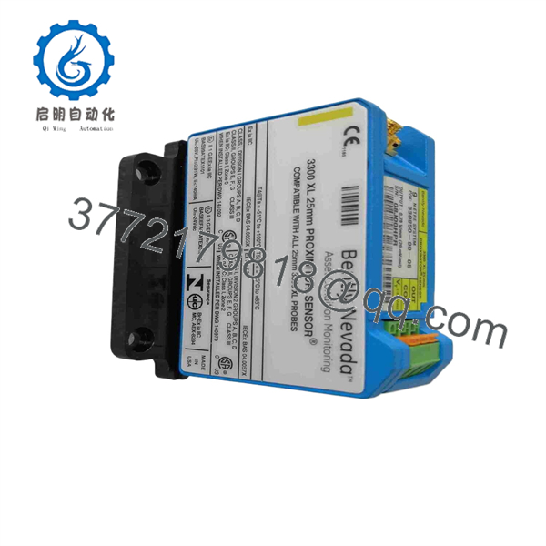
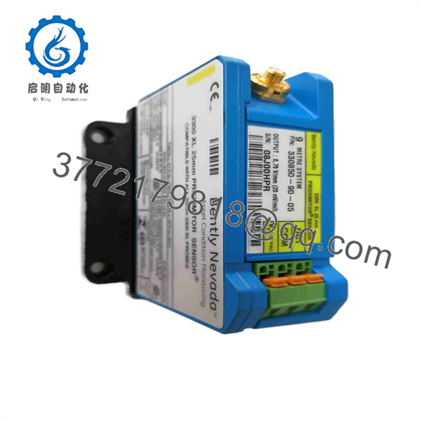
The Bently Nevada 330850-90-05 is a 3300 XL 25 mm Proximitor Sensor configured for a 9.0 m, panel-mount measurement system with multiple agency approvals. The 3300 XL 25 mm system is a three-piece assembly—probe, extension cable, and Proximitor Sensor—and the specified sensitivity and linear range apply only to the complete matched system.
Product Introduction
The Bently Nevada 330850-90-05 is a panel-mount 3300 XL 25 mm Proximitor Sensor for long-range non-contact displacement measurement on critical rotating equipment. It conditions the eddy-current signal from a matched 25 mm probe and extension cable, providing a calibrated voltage output proportional to the gap between the probe tip and a conductive target.
This sensor is typically applied where an 8 mm proximity system does not provide enough travel range, including steam-turbine differential expansion, rotor expansion, axial movement, thrust-bearing wear, and large machine position measurements. The 90 code defines a 9.0 m total system length and panel mounting; 05 identifies the multiple-approvals option.
330850-90-05
330850-90-05
Troubleshooting Quick Reference
| Symptom | Possible Cause | Relevance to This Part | Quick Check Method | Recommendation |
|---|---|---|---|---|
| No signal output from the Proximitor | Missing negative DC supply, open return, failed fuse, loose terminal, failed sensor | ✅ High | Measure the DC supply directly at the sensor terminals with a calibrated meter. Confirm the voltage is within the approved supply range and inspect terminal torque. | Restore stable supply and wiring first. Replace the 330850-90-05 only after confirming supply, return, and output wiring are intact. |
| Position or differential-expansion reading is outside normal range | Probe gap changed, wrong cable length, probe bracket movement, target movement, sensor mismatch, cable damage | ✅ High | Measure the sensor’s DC output and compare it with baseline commissioning values. Verify the probe, extension cable, and sensor labels form the correct 9.0 m system. | Treat a sudden displacement change as a possible machinery condition. Verify the physical probe mount and machine position before changing hardware. |
| Output is noisy or intermittent | Cable shield damage, loose ClickLoc connector, poor cable routing, EMI, moisture, sensor degradation | ✅ Medium | Inspect the full cable route, connector locking, cable jacket, shield treatment, and nearby VFD or high-current power wiring. Compare with a known-good channel. | Correct connector, routing, and shielding faults before replacing the Proximitor Sensor. |
| Output remains fixed high or low | Open probe, shorted extension cable, failed probe, wrong sensor chain, internal Proximitor failure | ✅ Medium | Isolate equipment under the approved machinery-protection procedure. Check supply, connector condition, cable continuity, and compare output with a known-good matched loop. | Diagnose probe and cable faults first. Replace the 330850-90-05 only after the field-side sensor chain is verified. |
| Reading changes after replacement | Incorrect 9.0 m system length, incompatible probe/cable, altered mechanical gap, sensor not fully connected, target material difference | ✅ High | Compare old and new labels, total cable length, probe position, and output voltage. Confirm the entire three-piece transducer system is matched. | Do not adjust DCS scaling or alarm limits to hide a changed reading. Validate the complete measurement chain first. |
| Sensor output drifts with cabinet temperature | Poor enclosure ventilation, heat source near panel, supply-voltage drift, deteriorating electronics | ✅ Medium | Trend output against cabinet temperature and supply voltage. Inspect the installation location and check for heating from adjacent equipment. | Correct thermal conditions. Replace the sensor if drift persists within the specified ambient range and with a stable supply. |
| Machinery alarm or trip occurs immediately after installation | Incorrect sensor chain, probe-gap error, cable mismatch, wiring error, alarm configuration mismatch, real machinery movement | ✅ High | Compare pre-maintenance and post-maintenance baseline readings. Verify all wiring, probe gap, sensor labels, and alarm configuration under controlled test conditions. | Treat the alarm as valid until the measurement chain and machine condition are proven correct. |
| DCS display is wrong but local monitor is correct | Incorrect analog scaling, polarity, input configuration, signal isolator fault, ground-reference issue | ❌ Low | Measure the sensor output and compare it with the monitor input and DCS engineering value. | Correct the monitor/DCS signal path before replacing a healthy sensor. |
| Sensor terminals show corrosion or moisture | Cabinet ingress, loose gland, chemical vapor, contaminated enclosure, washdown exposure | ✅ Medium | De-energize and inspect terminals, housing, cable entry, connectors, and cabinet seals. | Replace damaged hardware and eliminate the moisture or chemical source before recommissioning. |
| Fuse opens or sensor overheats | Reverse polarity, wiring short, damaged cable, failed sensor, unsuitable supply connection | ✅ High | Isolate the circuit and inspect supply wiring against the approved drawing. Check cable insulation and resistance before re-energizing. | Do not increase fuse size. Correct the wiring or cable fault before replacing the Proximitor Sensor. |
❗ The 9.0 m system length is part of the calibration. The 330850-90-05 requires a matched 25 mm probe, extension cable, and sensor combination totaling 9.0 m. Do not splice or substitute a different cable length because the connectors fit. A mismatched system can change the voltage-to-displacement relationship.
❗ Do not confuse a real movement alarm with a bad sensor. This product often monitors differential expansion, axial position, or thrust movement. A sudden value shift can indicate actual thermal growth, rotor movement, probe-bracket shift, or bearing wear. Check mechanical conditions before clearing alarms.
❗ Do not use an 8 mm sensor chain as a substitute. The 3300 XL 25 mm system has a different measurement range and sensitivity from the 3300 XL 8 mm system. The 25 mm Proximitor, probe, and extension cable must be matched as one system.
❗ Approval option must match the installation. The 05 suffix is commonly described as multiple agency approvals, but verify the exact unit’s nameplate and certificates against the site area classification and installation requirements. A similar-looking unit without the required certification is not an acceptable replacement.
If the fault remains unclear, provide technical support with photos of the 330850-90-05 label, connected probe and cable labels, terminal wiring, supply-voltage measurement, DC output voltage, baseline position values, monitor diagnostics, and the current machinery operating condition. Keep these checks in mind and you will save yourself 90% of typical rework time.
Frequently Asked Questions (FAQ)
What is the Bently Nevada 330850-90-05?
The 330850-90-05 is a Bently Nevada 3300 XL 25 mm Proximitor Sensor. It conditions a 25 mm eddy-current proximity probe signal and produces a voltage output proportional to the gap between the probe tip and a conductive machine target.
What does the 90 option mean?
The 90 option specifies a 9.0 m total system length and panel mounting. The total electrical path of the matched probe, extension cable, and Proximitor Sensor must meet the 9.0 m configuration.
What does the 05 suffix mean?
The 05 suffix is described as the multiple agency approvals option. Always verify the exact nameplate and applicable certificates before installing it in a hazardous or regulated area.
What does a 25 mm Proximitor system measure?
It measures non-contact distance to a conductive target over a large range. Typical uses include differential expansion, rotor expansion, axial position, thrust-bearing wear, and other large-travel displacement measurements on turbines and heavy rotating machinery.
Is this a 4–20 mA transmitter?
No. The 3300 XL 25 mm system uses a voltage output proportional to displacement. Public technical data lists a nominal sensitivity of 0.78 V/mm or 20 mV/mil. Do not wire it directly to a 4–20 mA input unless approved signal-conversion hardware is part of the design.
Can I use a different extension-cable length?
No. The probe, extension cable, and Proximitor Sensor form a matched, calibrated system. A different cable length, a field splice, or a mixed component family can change sensitivity and linearity, leading to false position values and incorrect alarms.
Can I replace the sensor while the machine is running?
Do not assume that is acceptable. Removing or rewiring the sensor can create a NOT OK condition, disturb position monitoring, generate false alarms, and affect machinery protection. Follow the plant’s approved bypass, alarm-management, permit, and return-to-service process.
Is the 330850-90-05 obsolete, and should I keep a spare?
Treat it as a specialized machinery-protection spare. The 3300 XL 25 mm system is installed in demanding turbine and heavy-rotating-equipment applications, so a failed sensor can remove critical displacement visibility. Keep a verified spare only if it matches the full 9.0 m, panel-mount, approval configuration, and retain probe/cable records, baseline output values, alarm settings, and installation drawings with the spare.



