
 WhatsApp: +86 16626708626
 Email:
  Phone: +86 16626708626
Description
3. Key Technical Specifications
| Parameter | Value |
|---|---|
| Manufacturer | Bently Nevada |
| Model Number | 146031-01 |
| Associated Module | 3500/22M TDI |
| Product Type | Transient Data Interface (TDI) I/O Module |
| System Family | Bently Nevada 3500 Series |
| Primary Function | Rack Communication Interface |
| Ethernet Interface | 10Base-T / 100Base-TX |
| Connector Type | RJ45 Ethernet |
| Communication Role | System 1 and Host Integration |
| Supported Protocols | Ethernet-Based TDI Communications, Modbus Integration |
| Rack Position | Associated with Slot 1 TDI Installation |
| Dynamic Data Capture | Supported with Channel Enabling Option |
| Static Data Collection | Standard Function |
| Compatible Monitors | 3500/40M, 3500/42M, 3500/44M, 3500/60 Series |
| TMR Support | Supported with TMR TDI Configuration |
| Operating Temperature | -30 °C to +65 °C |
| Storage Temperature | -40 °C to +85 °C |
| Humidity Rating | 95% Non-Condensing |
| I/O Module Weight | Approximately 0.20 kg |
| Country of Manufacture | USA |
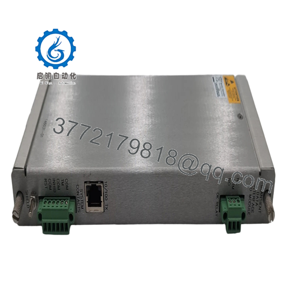
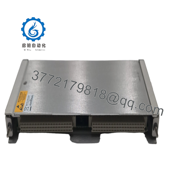
The Bently Nevada 146031-01 is the Ethernet I/O module used with the 3500/22M Transient Data Interface (TDI). It provides communication between the 3500 machinery protection rack and external systems such as System 1®, DCS platforms, SCADA systems, and maintenance workstations. The module supports steady-state monitoring data as well as optional transient waveform acquisition for startup, shutdown, and machinery event analysis.
4. Product Introduction
The Bently Nevada 3500/22M 146031-01 is a Transient Data Interface (TDI) Ethernet I/O module used within the 3500 Machinery Protection System. It serves as the communication gateway between rack-mounted monitoring modules and external diagnostic, monitoring, and control systems.
In field installations, the 146031-01 is commonly deployed where operators require access to vibration, position, speed, and transient waveform data through System 1 software or plant-wide DCS networks. Unlike older 3500/20 Rack Interface Modules, the 3500/22M architecture combines rack interface functionality with advanced data collection capability inside a single platform.

- 3500/22M 146031-01
- 3500/22M 146031-01
5. Installation & Configuration Guide
Stage 1: Pre-Installation Preparation (10 Minutes)
⚠️ Safety First
- Notify operations personnel before maintenance.
- Confirm machinery protection coverage during maintenance activities.
- Place affected monitoring channels into approved maintenance status.
- Lock out and tag out cabinet power where applicable.
- Wait at least 5 minutes for rack power supplies to discharge.
Tools Required
- Grounded ESD wrist strap
- ESD work mat
- PH1 screwdriver
- Fluke 115 multimeter
- Laptop with 3500 Configuration Software
- Ethernet patch cable
- Smartphone camera
Data Backup
- Backup the current 3500 rack configuration.
- Export System 1 communication settings.
- Record:
- Rack IP address
- Network settings
- Modbus mapping
- Firmware revision
- Photograph:
- Ethernet connections
- Rack slot layout
- Front panel indicators
❗ Always document the existing firmware revision before removal. I’ve seen replacement TDIs come online physically but refuse proper communication with older System 1 deployments because firmware families didn’t match.
Stage 2: Removing the Old Module (5 Minutes)
- Open rack access cover if installed.
- Disconnect Ethernet and communication cables.
- Label all network connections.
- Release retaining hardware.
- Pull the TDI assembly straight out.
⚠️ Do not twist the module during removal. The backplane connectors can be damaged surprisingly easily.
- Inspect:
- Rack connector alignment
- Dust buildup
- Corrosion
- Backplane condition
⚠️ Important
Retain the original module until complete communication testing is finished.
Stage 3: Installing the New Module (10 Minutes)
1. ESD Preparation
- Wear grounded wrist strap.
- Verify exact model number:
- 146031-01
If replacing a complete TDI assembly, verify the associated 3500/22M module revision as well.
2. Configuration Clone (Critical)
Verify:
- Ethernet configuration
- IP addressing
- Modbus settings
- System 1 communication parameters
- TMR configuration if installed
❗ This is one of the easiest places to lose hours during commissioning. Engineers often focus on the hardware swap and forget that network settings are what actually bring the rack back online.
3. Install Module
- Align with rack guides.
- Insert evenly.
- Fully seat the connector.
- Secure retaining hardware.
4. Restore Cabling
- Reconnect Ethernet connection.
- Verify cable routing.
- Confirm network switch assignments.
- Check grounding continuity.
Self-Checklist
- Correct module verified
- Firmware documented
- Ethernet connected
- Rack seated correctly
- Configuration backed up
- ESD procedures followed
Stage 4: Power-On & Testing (15 Minutes)
Pre-Power Check
- Verify rack grounding.
- Measure supply voltage.
- Inspect communication cables.
Power-Up Procedure
- Energize rack power.
- Observe front panel indicators.
Expected behavior:
- OK LED = Green
- Fault LED = Off
- Ethernet Activity LED = Flashing
- Connect using 3500 Configuration Software.
- Verify:
- Module recognition
- Rack communication
- Network connectivity
- Firmware revision
- Validate System 1 connectivity.
- Verify monitor data visibility.
- Confirm waveform acquisition if enabled.
⚠️ Troubleshooting Note
- No Ethernet Communication: Verify IP settings and switch configuration.
- System 1 Offline: Check TDI firmware compatibility.
- Intermittent Data Collection: Inspect network quality and grounding.
- Rack Communication Fault: Verify module seating and rack configuration.
Common Field Pitfalls Engineers Encounter
❗ Firmware Revision Mismatch
This issue appears constantly in older 3500 installations.
I worked a compressor station outage where a replacement TDI installed perfectly but would not exchange data with the existing System 1 server. The root cause was a firmware mismatch between rack components.
Avoidance: Record firmware versions before replacement and request matching revisions when sourcing inventory.
❗ IP Address Configuration Errors
A surprising number of communication failures come down to incorrect network settings.
The hardware passes self-tests, but nobody can see the rack.
Avoidance: Export configuration files before removal and verify addressing before startup.
❗ Incorrect TMR Configuration
In Triple Modular Redundant systems, TDI configuration affects monitor comparison logic.
An improperly configured replacement can generate nuisance diagnostics.
Avoidance: Verify TMR settings before energizing.
❗ Power Supply Margin Problems
Adding communication modules and network hardware can increase rack loading.
I’ve seen older installations operating near supply limits for years until one hardware replacement finally exposed the problem.
Avoidance: Maintain at least 20% available power margin.
❗ Electrostatic Discharge (ESD)
Communication processors are highly sensitive to static damage.
I once watched a contractor unpack a TDI board directly on a painted steel panel. The module powered up but lost Ethernet communication intermittently for the next two days.
The board eventually had to be replaced again.
Avoidance: Ground strap, ESD mat, anti-static handling every time.
Keep these checks in mind and you’ll save yourself 90% of typical rework time.
6. Frequently Asked Questions (FAQ)
Q1. What exactly does the 146031-01 module do?
The 146031-01 is the Ethernet I/O portion of the 3500/22M Transient Data Interface system.
It provides communication between the 3500 rack and external systems including:
- System 1
- DCS platforms
- SCADA systems
- Maintenance workstations
Without a properly functioning TDI interface, external access to rack data becomes limited or unavailable.
Q2. Is the 3500/22M 146031-01 obsolete?
Yes.
The 3500 platform remains widely installed, but many 146031-01 modules now come from:
- New Surplus inventory
- Strategic spare-part programs
- Refurbished stock
Availability can fluctuate significantly depending on refinery, power generation, and oil & gas outage demand.
Q3. Can I hot-swap the 146031-01 module?
No.
Bently Nevada machinery protection systems are not designed for casual live replacement of communication hardware.
Removing the TDI under power can interrupt rack communications and generate system events.
Power down the rack before replacement.
Q4. Will replacing the TDI affect machinery protection?
Normally no.
The TDI itself is not part of the critical protection voting path.
It handles communication and data collection functions rather than direct protection logic.
However, loss of TDI communication can affect diagnostics and external monitoring visibility.
Q5. What software is required to configure the 3500/22M?
Typically:
- Bently Nevada 3500 Configuration Software
- System 1 Machinery Management Software
These tools are used to configure communication settings, monitor assignments, and transient data collection functions.
Q6. What testing should be completed before shipment?
A proper supplier should perform:
- OEM label verification
- Serial number traceability inspection
- Visual inspection for corrosion and repair marks
- Power-on rack testing
- Ethernet communication verification
- System 1 communication testing
- 24-hour thermal operation test
- 500 V insulation resistance test (>10 MΩ)
- Firmware documentation
- QC sign-off and ESD packaging
Test reports and startup videos should be available upon request.
Q7. What is the most common mistake during replacement?
Skipping the network documentation.
Honestly, hardware installation is usually the easy part.
The problem starts when nobody records:
- IP address
- Network mask
- Modbus mapping
- Firmware version
Then the rack powers up and nobody can communicate with it.
I’ve seen engineers spend an entire shift troubleshooting a perfectly healthy module because the original addressing information was never documented. That mistake is far more common than actual hardware failure.


