
 WhatsApp: +86 16626708626
 Email:
  Phone: +86 16626708626
Description
Key Technical Specifications
| Parameter | Option Code / Value | Specification Details |
| Base Model | 3500/25 | Enhanced Keyphasor Module Architecture |
| Number of Channels | -02 | Two half-height cards providing 4 total channels |
| I/O Module Type | -05 | Isolated I/O module with External Terminations |
| Agency Approval | -01 | CSA/NRTL/C (Class I, Division 2, Groups A, B, C, D) |
| Input Signal Range | — | +0.8 V to −21.0 V (Non-Isolated) / +5 V to −11 V (Isolated) |
| Input Frequency | — | 0.017 Hz to 20 kHz (1 to 1,200,000 cpm) |
| Input Impedance | — | 21.8 kΩ minimum |
| Accuracy Matrix | — | Speed/Frequency signal accurate to ±1 cpm |
| Power Consumption | — | 3.2 W typical per half-height card |
| Operating Temperature | — | −30 to +65 °C (−22 to +149 °F) |
Product Introduction & Supply Chain Strategy
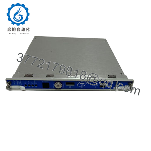
The Bently Nevada 3500/25-02-05-01 is an Enhanced Keyphasor Module configuration consisting of two half-height, two-channel cards that supply a total of four independent phase reference channels to a 3500 monitoring rack. The module processes raw timing pulses from proximity probes or magnetic pickups when a shaft mark passes the transducer. This once-per-turn or multi-event signal is vital for calculating exact rotative speeds and synchronous vector metrics, including 1X vibration amplitude and phase angle characteristics across the entire machine train.
Procuring this specific configuration as a New Surplus asset represents an ROI-driven MRO sourcing strategy. Keyphasor cards act as the diagnostic reference backbone for predictive maintenance; if a phase tracking loop drops out, your monitoring system loses its vector processing alignment, blinding engineering teams to orbital shaft shifts. Utilizing used or refurbished alternatives risks capturing degraded tracking pulses due to deteriorated internal optocouplers or micro-fractured isolation barriers. Stocking a factory-sealed, unused surplus card set delivers instant component-level availability, stabilizes Total Cost of Ownership (TCO), and completely eliminates vendor lead time variability.

- 3500/25-02-05-01
Installation & Configuration Guide
Stage 1: Pre-Installation (Prep & Safety)
- Isolate the target half-height slot pairs inside the left sector of the 3500 main rack.
- Ensure downstream diagnostic or active trip relays driven by phase/speed thresholds are safely bypassed to prevent an inadvertent plant trip.
- Secure your grounded ESD wrist strap tightly to the bare metal structural ground point of the machine panel.
- Launch the 3500 Rack Configuration utility and archive the system configuration (.w1) file before removing any hardware.
Stage 2: Removal
- Unthread the captive structural face screws bounding the upper and lower half-height cards in the slot panel.
- Go to the rear of the rack chassis and disconnect the interface cable running to the external termination block assembly.
- Pull the card extraction handles outwards smoothly, sliding both half-height assemblies horizontally out along the guide channels to prevent bending the gold backplane connection paths.
Stage 3: Installation (Clone & Seat)
- Unbox the new surplus 3500/25-02-05-01 module set inside an ESD-safe zone. Verify internal jumper matrices match your plant engineering specifications for isolated signal thresholds.
- Insert the main modules into their designated upper and lower half-height configurations inside the rack slot chassis.
- Slide the assemblies inward until the edge pins seat squarely into the backplane, then lock down the front panel captive hardware.
Stage 4: Power-On & Testing
- Re-couple the external termination block interface cable to the rear matching I/O module faceplate.
- Re-energize the rack slot. The front panel OK LED indicator must glow solid green.
- Download the stored configuration profile (.w1 file) to the slot via your system interface. Confirm the Bypass light responds appropriately and that the signal thresholds match current shaft rpm readouts.
Firmware/Software Versions & Upgrade Notes
The 3500/25-02-05-01 Enhanced Keyphasor Module introduces internal microprogrammable signal logic designed to be backward compatible with standard, legacy 3500/25 systems. However, to leverage the expanded multi-event tracking matrices or automated threshold adjustments, your 3500 Rack Configuration software must be at Version 3.3 or higher, and the 3500/22M TDI module firmware must align with the current card generation.
When performing a field swap with a new surplus module, verify the firmware revision embedded on the replacement board matches your existing baseline. A severe mismatch between the firmware on the Keyphasor card and the Rack Interface Module can block parameter downloads, causing a persistent configuration fault code. If firmware alignment is necessary, always perform the adjustment in a non-operational test rack environment before live deployment.
Frequently Asked Questions (FAQ)
What does the “-02” option code signify on this specific model?
The “-02” option specifies that this configuration is a 4-channel Keyphasor system. It includes two separate, half-height 2-channel main cards that install together in a single rack slot position, giving the system the ability to track up to four independent phase and speed reference sensor points simultaneously.
Why is the “-05” isolated external termination option important?
The “-05” option designates an isolated I/O module configuration designed to interface with an external termination block. This provides galvanic isolation for applications where your Keyphasor signals are tied in parallel to multiple external diagnostic systems or data loggers. The isolation prevents ground loops and electrical noise from reflecting back into the main 3500 protective rack logic.
Is this 3500/25-02-05-01 card assembly factory new or a clean repair?
This item is 100% genuine New Surplus inventory. It has never been deployed in an active production facility, never subjected to industrial thermal stress, and contains no component-level aftermarket repairs. It ships fully clean and preserved in its original factory protective packaging.
Will this card set arrive pre-configured for my magnetic pickup settings?
No, surplus components are kept in an unconfigured factory state to maximize installation versatility. You must use your plant’s 3500 Rack Configuration software to set specific parameters, such as probe types (proximity vs. magnetic pickup), manual or automatic threshold levels, and hysteresis levels, before putting the channels into service.
What kind of warranty covers this specific Keyphasor assembly?
Every New Surplus Bently Nevada component we supply includes our comprehensive 1-year product replacement warranty. This gives your procurement team identical structural safety windows as a factory order while maintaining capital budget efficiency.



