
 WhatsApp: +86 16626708626
 Email:
  Phone: +86 16626708626
Description
Key Technical Specifications
- Manufacturer: Bently Nevada
- Product Family: 3500 Machinery Protection System
- System Architecture: Modular rack-based monitoring and protection platform
- Rack Size: 14-slot, 19-inch rack
- Rack Variants: Standard 3500 rack and mini-rack configurations are available within the product family
- Power Supply Options: AC and DC power-supply configurations, depending on rack and module selection
- Monitoring Inputs: Proximity probes, velocity sensors, accelerometers, and other compatible machinery-monitoring transducers
- Protection Functions: Overspeed, vibration, position, speed, differential expansion, eccentricity, and other machine-specific protection functions depending on installed modules
- Communication: System communications depend on installed interface and communication modules
- Configuration Software: Bently Nevada 3500 configuration tools and compatible system software
- Relay Outputs: Configured through installed relay modules
- System Expansion: Modular architecture allows monitoring modules to be selected according to the machinery protection requirement
- Installation: Panel/rack mounting
- Application: Rotating machinery monitoring and protective shutdown
- Important Compatibility Factor: Exact module combination, rack type, firmware, power supply, keyphasor configuration, and transducer type must be checked before replacement
Product Introduction
The Bently Nevada 3500 is a rack-based machinery protection and condition-monitoring platform used to continuously monitor rotating equipment and initiate protective action when configured alarm or trip limits are exceeded. Typical installations include steam and gas turbines, compressors, pumps, generators, and large motors.
The 3500 is not a single monitoring card. It is a system platform consisting of a rack, power supply, interface hardware, monitoring modules, relay modules, and associated transducers. For replacement work, the exact 3500 rack configuration must be identified before ordering.
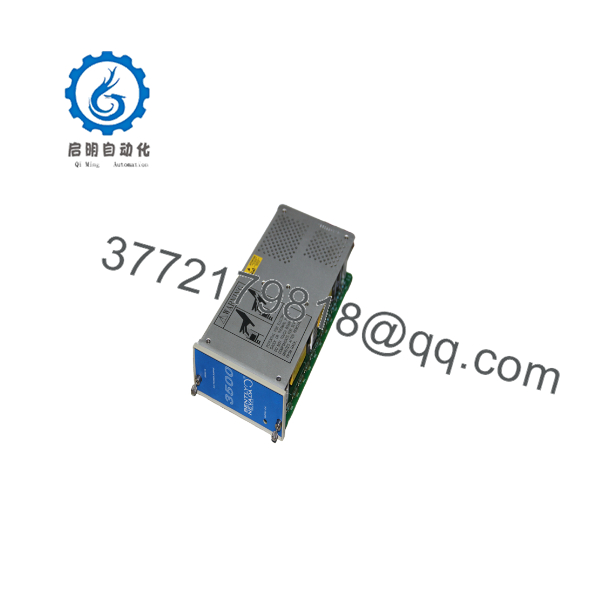
3500
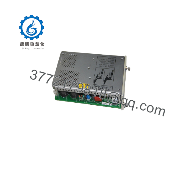
3500
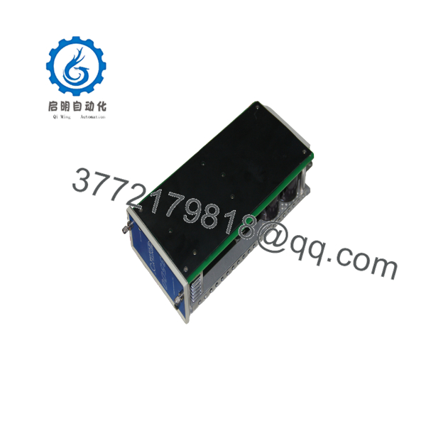
3500
Installation & Configuration Guide
Stage 1: Pre-Installation Preparation — Approximately 10 Minutes
⚠️ Safety First: Coordinate the work with operations and place the machine in the required safe condition. Follow the plant’s lockout/tagout procedure before removing energized 3500 hardware. For machinery connected to a trip circuit, confirm the approved bypass or shutdown procedure before disconnecting protection channels.
Tools Required:
- ESD wrist strap
- Appropriate screwdriver set
- Calibrated digital multimeter
- Wire labels
- Smartphone or camera
- Laptop with the applicable Bently Nevada configuration software
- Approved electrical test equipment for the specific transducer circuits
Data Backup:
- Record the complete 3500 rack part number and serial number.
- Photograph the complete rack from the front.
- Photograph every installed module.
- Record each module’s slot position.
- Record module part numbers and revisions.
- Photograph all relay and terminal wiring.
- Record power-supply type and input voltage.
- Document transducer types and channel assignments.
- Save the existing configuration file if available.
- Record alarm and trip setpoints before making changes.
⚠️ Do not identify a 3500 system solely by the word “3500.” A 3500/15 power supply, 3500/22 transient data interface, 3500/42M proximity monitor, and 3500/32 relay module perform very different functions.
Stage 2: Removing the Existing Module — Approximately 5 Minutes
For a module-level replacement:
- Verify the machine is in the approved maintenance state.
- Follow the site’s electrical isolation procedure.
- Identify the module slot from the documented rack layout.
- Record the module part number and revision.
- Disconnect applicable field wiring according to the manufacturer’s procedure.
- Release the module retaining mechanism.
- Pull the module straight from the rack.
- Inspect the rack connector for contamination, bent contacts, or mechanical damage.
- Place the removed module in an ESD-safe container.
⚠️ Do not disturb adjacent protection channels unnecessarily. On a running machinery protection system, changing multiple channels simultaneously makes subsequent fault isolation much harder.
Stage 3: Installing the Replacement Module — Approximately 5–10 Minutes
- Verify the complete module part number before installation.
- Compare the replacement with the original module.
- Confirm the required module type and slot position.
- Put on the grounded ESD strap.
- Check the rack connector for contamination or damage.
- Insert the module straight into the correct slot.
- Engage the module retention mechanism.
- Reconnect field wiring according to the documented terminal assignment.
- Verify shielding and signal-ground connections.
- Confirm that no field conductor is loose or incorrectly landed.
Configuration Clone — Critical
Before returning the machinery protection system to service:
- Record the existing channel configuration.
- Verify transducer type.
- Verify sensor polarity and signal range.
- Verify channel alarm setpoints.
- Verify danger/trip setpoints.
- Verify relay logic.
- Verify voting logic where applicable.
- Verify Keyphasor/speed references.
- Compare the replacement module’s firmware or hardware revision where applicable.
- Restore the approved configuration.
Self-Checklist:
- Correct module part number
- Correct rack slot
- Firmware/revision checked
- Transducer type verified
- Wiring verified
- Shielding verified
- Alarm setpoints documented
- Trip setpoints documented
- Relay logic checked
- Module fully seated
Stage 4: Power-On & Functional Testing — Approximately 10–20 Minutes
- Perform a complete wiring inspection before energizing the rack.
- Verify the installed power supply matches the rack’s required input.
- Energize the 3500 rack according to the approved procedure.
- Observe module LEDs and rack status.
- Connect the engineering workstation using the appropriate interface.
- Verify that the replacement module is recognized.
- Compare configuration parameters with the approved backup.
- Verify transducer input status.
- Check channel OK status.
- Verify alarm thresholds.
- Verify relay status and voting logic.
- Perform a controlled functional test of the monitoring channel.
- Confirm the machinery trip path before returning the equipment to operation.
⚠️ Never bypass a machinery protection channel simply to clear a startup fault without an approved maintenance procedure. A disabled vibration or overspeed channel can remove a protective layer from high-energy rotating equipment.
Technical Pitfalls and Survival Guide
1. Firmware or Hardware Revision Mismatch
A replacement 3500 module may have a different revision from the installed unit. That does not automatically mean it is incompatible, but it must be checked against the existing rack configuration and system documentation.
2. Wrong Module in the Correct Slot
A common mistake is matching the physical dimensions rather than the function. A 3500 rack can contain several visually similar plug-in modules with completely different measurement functions.
3. Transducer Mismatch
A Bently Nevada proximity probe system is not interchangeable with an accelerometer input simply because both are used for vibration monitoring. Verify the transducer type, signal conditioning requirements, channel configuration, and calibration parameters.
4. Incorrect Alarm or Trip Setpoints
This is the dangerous one. Do not copy alarm values from a generic example. Setpoints must come from the machine protection specification, commissioning documentation, or approved plant configuration.
5. Relay Logic and Voting
A monitoring module may indicate a fault correctly while the protective relay logic remains incorrectly configured. Verify the complete path from sensor → monitor → logic → relay → shutdown system.
6. ESD
Use a grounded wrist strap when handling plug-in monitoring modules. Do not touch exposed circuit contacts unnecessarily.
Frequently Asked Questions (FAQ)
Is the Bently Nevada 3500 a single module?
No. The 3500 is a complete machinery protection platform. Individual products within the family include power supplies, rack interface modules, monitoring modules, relay modules, and communication hardware.
For procurement, asking for “a 3500” is not enough. The supplier needs the exact module or rack configuration.
What is the difference between the 3500 rack and a 3500 monitoring module?
The rack provides the mechanical, power, and backplane infrastructure. Monitoring modules perform specific measurement and protection functions. For example, a proximity/vibration monitoring application requires the appropriate monitor module and compatible transducer system.
The rack and module should therefore be treated as separate purchasing identifiers.
Can I replace a 3500 module while the rack is powered?
Do not assume that every 3500 module can be removed under power. Follow the specific Bently Nevada installation procedure for the module and the plant’s machinery-protection maintenance procedure.
For critical turbine or compressor protection, planned isolation is preferable unless the documented system procedure specifically authorizes energized replacement.
Will replacing a 3500 module erase the machinery protection settings?
Do not rely on the replacement module to contain the original configuration. Back up the existing configuration before replacement. Record channel assignments, transducer information, alarm limits, danger limits, relay logic, and other machine-specific parameters.
After installation, compare the replacement configuration against the approved baseline before returning the protection system to service.
Is the Bently Nevada 3500 obsolete?
The 3500 is a mature legacy machinery protection platform, but individual components have different lifecycle and availability situations. Do not assume that every 3500-series part has the same lifecycle status.
For an existing plant, identify the exact module number and current lifecycle status before making a long-term spare-parts decision.
Why is the price of a surplus Bently Nevada 3500 component lower than the OEM list price?
Surplus inventory can come from plant closures, project cancellations, excess inventory, or discontinued-system stock. Lower pricing does not by itself prove that a unit is counterfeit or defective.
The important questions are condition, traceability, exact part number, revision, testing history, and warranty. Request photographs of the actual unit and a test report when the application is safety-critical.
What information should I provide when ordering a Bently Nevada 3500 replacement?
Provide the complete part number, not just “3500.” Also provide:
- Installed rack type
- Module slot
- Complete module part number
- Hardware revision
- Firmware information where applicable
- Transducer type
- Existing configuration
- Machine type
- Required condition: New Original / New Surplus or Refurbished / Tested
For a critical machinery protection application, verify the replacement against the applicable Bently Nevada documentation before installation. A visually similar module is not sufficient evidence of functional compatibility.



