
 WhatsApp: +86 16626708626
 Email:
  Phone: +86 16626708626
Description
Key Technical Specifications
| Parameter | Specification Details |
| Manufacturer | Berghof Automation GmbH |
| Order Code | CE3CPU-1131 (203100020-00903) |
| Programming System | CODESYS (IEC 61131-3 languages: ST, LD, FBD, SFC, IL) |
| Supply Voltage | 24 VDC (SELV, 18 to 31.2 VDC range) |
| Power Consumption | Max 0.5 A at 24 VDC |
| Ethernet Interface | 1x RJ45 10/100 Mbit/s (Modbus TCP, Ethernet/IP, CODESYS target) |
| Fieldbus Interfaces | 2x CAN Bus / CANopen (DB9 connectors), 1x Serial RS232/RS485 |
| Onboard Digital I/O | Integrated 24 VDC digital input and output screw terminal channels |
| Status Display | Onboard diagnostic LEDs (Power, Run, Error, CAN Status) |
| Operating Temperature | 0°C to +60°C |
Product Introduction & Supply Chain Strategy
The Berghof CE3CPU-1131 is an all-in-one compact PLC controller engineered for distributed control, motion orchestration, and remote I/O processing. Powered by the CODESYS IEC 61131-3 development platform, the CE3CPU-1131 acts as a centralized master node over Ethernet and CANopen networks. Its compact DIN-rail form factor incorporates field communication interfaces (Ethernet RJ45, dual CAN ports, RS232/RS485) alongside integrated digital I/O channels directly on the module base plate.
Procuring the CE3CPU-1131 as New Surplus inventory offers immediate machine recovery for critical packaging, material handling, and custom OEM machinery without long factory lead times. This product is a Brand New Surplus unit. It is not used, not pulled from a decommissioned line, and not refurbished. All modules undergo physical inspection and electrical power checks to ensure original manufacturer reliability. Maintaining a spare CE3CPU-1131 on-site prevents long operational outages caused by power surge damage or port failures on industrial control networks.
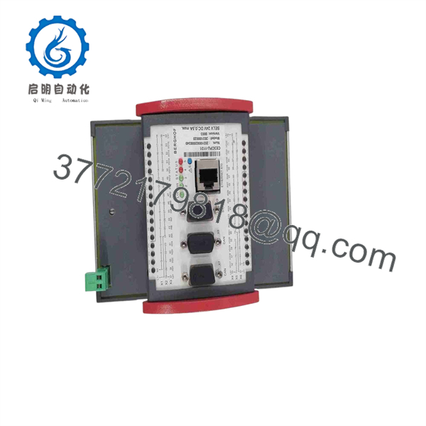
CE3CPU-1131
Installation & Configuration Guide
Stage 1: Pre-Installation (Prep & Safety)
- Disconnect incoming 24 VDC main power feed to the control cabinet (LOTO).
- Wear an ESD grounding wrist strap attached to an unpainted chassis earth point.
- Prepare the CODESYS project file matching the target application firmware version.
Stage 2: Physical Mounting & Wiring
- Snap the CE3CPU-1131 module onto the standard 35 mm DIN rail in the cabinet frame.
- Wire the 24 VDC power supply connector to the designated SELV power terminals, verifying proper polarity (+24V and 0V).
- Connect field communication lines: Ethernet RJ45 cable into port X10 and CANopen network lines into DB9 connectors X7/X8 with 120-ohm bus termination resistors attached at network ends.
Stage 3: Power-On & Diagnostic Verification
- Apply 24 VDC power to the controller module.
- Monitor front status LEDs during initialization: Power LED should hold steady green, and Run/Status LEDs will indicate software startup state.
- Connect a PC via Ethernet, scan for the unit’s default IP address in CODESYS, download project application code, and test digital I/O channel actuation.
Firmware/Software & Compatibility Notes
- CODESYS Platform: The is programmed using CODESYS. Ensure your development software matching target hardware target files (PLC target package) is installed on your engineering workstation prior to connecting.
- CANopen Network Termination: The dual CAN ports (X7/X8) require external 120-ohm termination resistors on the first and last physical devices on the fieldbus line to prevent communication signal reflections.
- IP Configuration: Default network settings can be adjusted using the Berghof Ethernet Configuration tool or directly through the CODESYS device management tab over the default IP subnet.
Frequently Asked Questions (FAQ)
Q: This unit is listed as New Surplus. How can I be sure it is not pre-owned or rebuilt?
A: This product is a Brand New Surplus unit. It is not used, not pulled from a decommissioned plant, and not refurbished. All modules undergo quality verification to ensure OEM-level reliability. Stock is acquired directly from canceled engineering projects, system integrator inventory holds, and factory spares.
Q: How do I back up or transfer the PLC program from an existing module?
A: Connect your programming PC to the Ethernet port (X10) using CODESYS. Perform a device scan, connect to the runtime target, and upload the source application project (if source code upload was enabled during original project download). Alternatively, flash memory parameters can be backed up via the system web interface or memory management utility.
Q: What warranty is provided with this Berghof CPU module?
A: Every Berghof module includes a full 1-Year functional replacement warranty. Prior to shipment, the module undergoes mechanical checks, pin condition checks, and power-up verification to ensure immediate operational readiness.



