
 WhatsApp: +86 16626708626
 Email:
  Phone: +86 16626708626
Description
Key Technical Specifications
| Parameter | Specification |
|---|---|
| Manufacturer | Bosch Rexroth / Indramat |
| Model | CLC-V02.3C-FW |
| Product Family | CLC-V |
| Product Type | Multi-Axis Coordinated Motion Control Card |
| System Architecture | VMEbus |
| Motion Network | SERCOS |
| SERCOS Medium | Fiber optic |
| Firmware Configuration | FW |
| Multi-Axis Capability | GPS firmware configuration is associated with up to 40 axes in available parts references |
| Host/Service Communication | ASCII CLC interface |
| Serial Communication Rate | 9,600 baud |
| Character Format | 8 data bits |
| Stop Bits | 1 |
| Parity | None |
| Primary Function | Coordinated servo motion control |
| Typical Application | Multi-axis machine and automation systems |
| Legacy Platform | Indramat CLC/VME motion-control architecture |
Specification Verification Note
There is a significant amount of inconsistent third-party technical data for this legacy part. For example, one supplier page assigns a Motorola 68020 processor and specific memory figures, while another database gives a completely different processor and I/O architecture.
Those conflicting values should not be treated as verified OEM specifications. For a replacement page, the safest engineering identification is the consistently supported information: CLC-V02.3C-FW, CLC-V family, VMEbus architecture, SERCOS interface, and FW/GPS motion-control configuration.
Product Introduction
The Bosch Rexroth Indramat CLC-V02.3C-FW is a legacy CLC-V VMEbus motion-control card used for coordinated multi-axis servo applications. It interfaces with compatible Indramat motion systems through a SERCOS fiber-optic ring and is associated with FW/GPS configurations intended for systems requiring coordinated motion across multiple axes.
This module is not a conventional PLC I/O card or standalone servo amplifier. It belongs to the motion-controller layer of the Indramat architecture. When replacing one, the exact CLC hardware revision, firmware configuration, VME rack, SERCOS ring, drive family, and stored motion program should all be checked before commissioning.
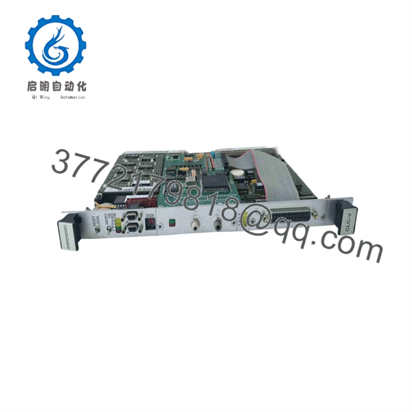
CLC-V02.3C-FW
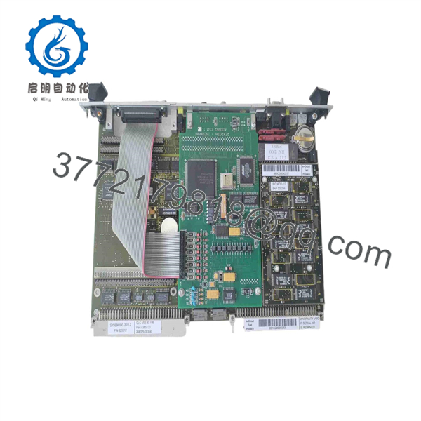
CLC-V02.3C-FW
Installation & Configuration Guide
Stage 1 — Pre-Installation Preparation
Approximate time: 30–45 minutes
- Apply the machine’s approved lockout/tagout procedure.
- Record the complete module designation: CLC-V02.3C-FW.
- Photograph the existing VME rack position and all connected interfaces.
- Record the installed Indramat drive family and SERCOS network topology.
- Back up the existing motion program, machine parameters, and firmware/configuration data where the service environment permits.
- Record the controlled-axis assignments and any GPS/multi-axis synchronization configuration.
- Verify that the replacement has the same CLC-V hardware and firmware designation.
⚠️ Do not substitute another CLC-V revision solely because the board appears mechanically compatible. Motion firmware and axis configuration can be revision-dependent.
Stage 2 — Removing the Existing Controller Card
Approximate time: 15–25 minutes
- Shut down the machine using the manufacturer’s prescribed sequence.
- Remove power from the VME system and verify the required discharge time.
- Label all external communication and SERCOS connections.
- Photograph connector positions before removal.
- Release the VME card retention hardware.
- Remove the CLC-V02.3C-FW using appropriate ESD precautions.
- Inspect the VME backplane connector for contamination, damaged contacts, or mechanical wear.
- Check the SERCOS fiber connector for damage before transferring it to the replacement unit.
Stage 3 — Installing CLC-V02.3C-FW
Approximate time: 20–30 minutes
- Verify the replacement label and board designation.
- Confirm the correct VME rack slot.
- Use ESD protection while handling the controller card.
- Carefully align the board with the VME guides.
- Seat the card fully into the backplane connector without excessive force.
- Secure the front-panel retaining hardware.
- Reconnect the SERCOS fiber-optic interface in its original transmit/receive arrangement.
- Reconnect any service or host communication cables.
- Confirm that the SERCOS ring topology has not been altered.
- Verify that all neighboring VME modules remain firmly seated.
Stage 4 — Power-On & Testing
Approximate time: 45–90 minutes
- Perform a final VME rack and connector inspection.
- Restore control power according to the machine procedure.
- Monitor the CLC controller diagnostic indicators during initialization.
- Verify that the expected firmware/configuration is recognized.
- Confirm SERCOS communication with the connected drives.
- Check each configured axis for communication and diagnostic status.
- Verify axis addressing and synchronization assignments.
- Run the machine initially with motion disabled or under the approved low-risk commissioning mode.
- Perform a controlled single-axis test before enabling coordinated motion.
- Verify interpolation, electronic gearing, synchronization, and machine-specific limits where applicable.
- Save the validated controller configuration after successful testing.
⚠️ Do not immediately execute a full multi-axis production cycle after replacing the CLC card. A firmware or axis-configuration mismatch can affect coordinated motion even when the SERCOS ring initially reports communication.
FAQ
What is the .3C-FW?
It is a Bosch Rexroth Indramat CLC-V motion-control card using VMEbus architecture and a SERCOS fiber-optic interface. Industrial parts references identify it as a multi-axis coordinated motion-control/servo-control module.
Is .3C-FW a servo amplifier?
No. It is a motion-control card, not the power stage that directly supplies motor current. It coordinates motion and communicates with compatible Indramat drive systems through the motion-control architecture.
What does the “FW” suffix mean?
The FW suffix identifies a firmware-configured version. Parts references specifically associate .3C-FW with a GPS firmware configuration and multi-axis motion-control functionality.
How many axes can .3C-FW control?
Some legacy parts databases identify the FW/GPS configuration with up to 40 axes in the overall system.
However, the actual number of simultaneously controlled axes depends on the complete CLC architecture, firmware, SERCOS configuration, drive topology, and application program. The 40-axis figure should therefore be treated as a system/configuration reference rather than a universal per-board rating.
Does .3C-FW use SERCOS?
Yes. Available CLC-V references consistently identify a SERCOS fiber-optic interface for the motion-control network.
Is .3C-FW still a current product?
It is a legacy Indramat product and is primarily encountered through surplus, refurbished, repair, and specialist industrial-automation channels. Current supplier catalogs still list the exact part number, but that does not indicate current OEM production.
Can .3C-FW replace .3-FW or .3-C-1?
Do not assume direct interchangeability. The CLC-V family contains multiple hardware and firmware variants, including .3-FW, .3-C-1, and .3C-FW.
Before replacement, compare the exact hardware designation, firmware, VME configuration, SERCOS setup, axis count, and machine application.
What should be checked before purchasing a replacement?
Verify:
- exact designation
- VMEbus rack and slot
- Existing CLC firmware/version
- SERCOS drive family
- Fiber-optic ring topology
- Axis configuration
- GPS/multi-axis synchronization requirements
- Motion program and parameter backup
- Board condition and repair/test documentation
For this legacy controller, matching the complete hardware and firmware designation is more important than matching the CLC family name alone.



