WhatsApp: +86 16626708626
 Email:
 Phone: +86 16626708626
Description
Core Product Summary
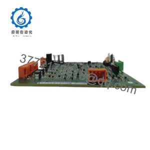
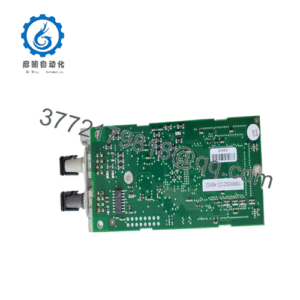
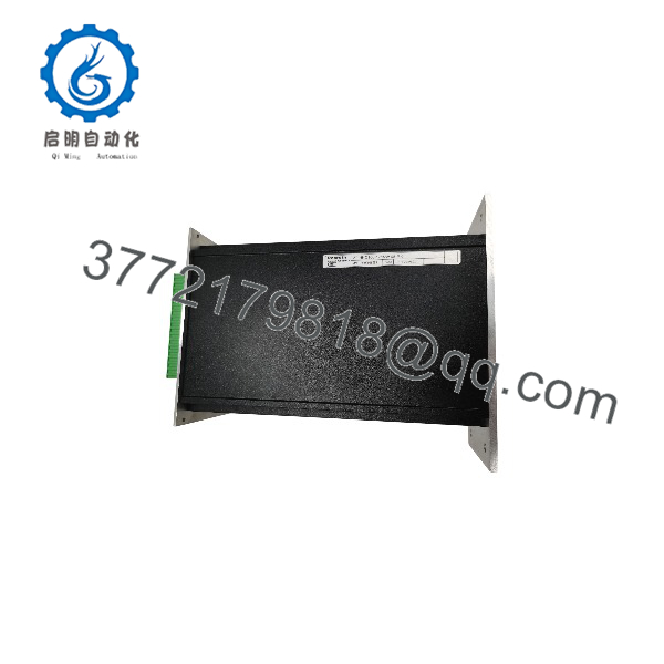
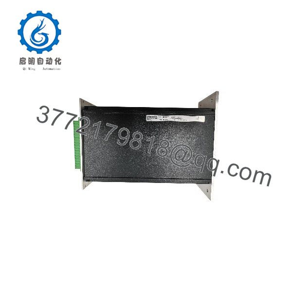
The Bosch Rexroth VT-HNC100-1-23W-08-0-0 is an HNC100 Digital Axis Controller configured for one hydraulic axis. It is a programmable closed-loop controller intended for electrohydraulic motion applications, with a wall-mount housing for cabinet installation.
This configuration provides eight digital inputs/outputs and PROFIBUS DP communication with a higher-level control system. The controller operates from an 18–36 VDC supply and is identified by Bosch Rexroth material number R900955334. It is designed for hydraulic closed-loop control applications where the controller coordinates command signals, axis feedback, and proportional-valve control.
Key Technical Specifications
| Parameter | Bosch Rexroth VT-HNC100-1-23W-08-0-0 |
|---|---|
| Manufacturer | Bosch Rexroth |
| Product family | HNC100 Digital Axis Control |
| Model designation | VT-HNC100-1-23W-08-0-0 |
| Material number | R900955334 |
| Axis configuration | One hydraulic axis |
| Component series | 23 |
| Housing type | Wall-mount housing |
| Digital I/O | Eight digital inputs/outputs |
| Fieldbus communication | PROFIBUS DP |
| Evaluation electronics | Without |
| Supply-voltage range | 18 to 36 VDC |
| Supply residual ripple | Less than 1.5 Vpp at 1 A |
| Recommended input fuse | 1.25 A |
| Commissioning interface | V24/RS-232 connection at X4 |
| Local CAN interface | X4 and X8 |
| Higher-level control interface | X5, PROFIBUS DP |
| Power connection | X6 |
| Controller role | Fieldbus slave |
| Installation environment | Control cabinet; do not install next to power electronics such as frequency converters |
Engineering Selection Highlights
- The
1in the type designation identifies a one-hydraulic-axis controller, making this model suitable for single-axis hydraulic closed-loop applications rather than multi-axis coordination. - The
23component series and complete suffixW-08-0-0must be matched exactly when replacing or configuring the controller, because HNC100 variants differ in housing, I/O count, bus interface, and evaluation electronics. - The
Wdesignation identifies a wall-mount housing, so cabinet space and mounting provisions should be planned for a panel- or wall-mounted controller rather than a plug-in Eurocard. - The
08designation identifies eight digital inputs/outputs, which defines the available discrete interface capacity for machine signals and control functions. - PROFIBUS DP communication allows the controller to operate as a slave to a higher-level automation system, so the master’s PROFIBUS configuration and network wiring must be planned accordingly.
- The 18–36 VDC supply range, less than 1.5 Vpp ripple requirement, and recommended 1.25 A input fuse define the electrical supply boundary for reliable operation.
- The controller requires careful signal and power-cable separation, shielded signal cabling, and installation away from power electronics such as frequency converters to limit electrical interference.
VT-HNC100-1-23W-08-0-0
VT-HNC100-1-23W-08-0-0
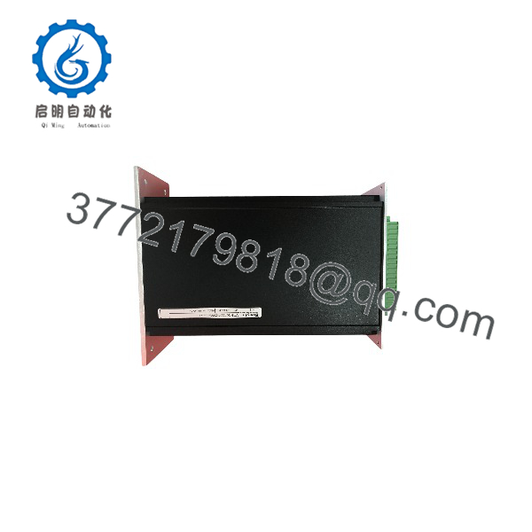
VT-HNC100-1-23W-08-0-0
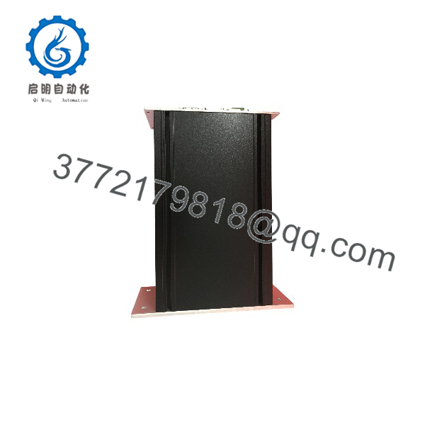
VT-HNC100-1-23W-08-0-0
System Compatibility & Integration Requirements
| Item / Dependency | Verified Compatibility or Requirement | Practical Note |
|---|---|---|
| Controller family | Bosch Rexroth HNC100 Digital Axis Control | The module is part of the HNC100 programmable digital axis-control family. |
| Axis configuration | One hydraulic axis | The 1 designation identifies the single-hydraulic-axis version. |
| Housing | Wall-mount housing | The W designation identifies the wall-mount housing configuration. |
| Digital I/O | Eight digital inputs/outputs | The 08 designation identifies the eight-channel digital I/O configuration. |
| Fieldbus | PROFIBUS DP | The controller functions as a PROFIBUS DP slave to a higher-level control system. |
| Commissioning interface | V24/RS-232 at X4 | Use the documented V24 cable and 9-pin D-SUB connection for PC communication. |
| Local CAN | X4 and X8 interfaces | Local CAN supports connection between HNC100 units; terminate the last unit with a 120 Ω plug terminator. |
| Power supply | 18–36 VDC, ripple below 1.5 Vpp at 1 A | Install the power supply close to the controller and use a recommended 1.25 A input fuse. |
| Encoder supply | 5 V encoder supply up to 150 mA per axis; 24 V encoder supply up to 200 mA per axis | Confirm the connected measuring-system supply requirement before wiring. |
| Signal wiring | Shielded copper-braid signal cables | Keep signal and load cables physically separated and avoid parallel routing. |
Dimensions, Mounting & Connection Notes
- The controller uses a wall-mount housing intended for installation in a control cabinet.
- The housing backpanel can be grounded for high-frequency purposes by connecting it to the control-cabinet backpanel using four M4 screws.
- The power connection is made at X6: pin 1 is shield, pin 2 is GND, and pin 3 is 18–36 VDC.
- The V24/RS-232 commissioning connection uses X4 and a 9-pin D-SUB cable; Bosch Rexroth recommends LiYCY 5 × 0.14 mm² cable.
- X5 provides the PROFIBUS DP interface to the higher-level control system.
- X4 and X8 provide COM/local CAN connections.
- For multiple HNC100 units connected through local CAN, the last controller requires a 120 Ω plug terminator between pins 8 and 9 at X8.
- Signal cables should use copper-braid shielding, be kept physically separate from load cables, and avoid routing through strong magnetic fields.
- Power-supply and return conductors should be installed together or twisted.
Detailed Product Overview
The Bosch Rexroth VT-HNC100-1-23W-08-0-0 is a member of the HNC100 Digital Axis Control family. It is configured for one hydraulic axis, uses a wall-mount housing, provides eight digital inputs/outputs, and communicates with a higher-level control system through PROFIBUS DP. Its Bosch Rexroth material number is R900955334.
The HNC100 family is a programmable digital axis-control platform intended for closed-loop control of hydraulic drives. The -1 in this model designation identifies the single-hydraulic-axis version, while -23 identifies the component series. The W suffix identifies the wall-mount housing, and 08 identifies the eight-channel digital I/O configuration. The final 0-0 portion of the designation identifies the configured option set, including the absence of additional evaluation electronics.
The controller operates from an 18–36 VDC supply. Bosch Rexroth specifies a residual ripple content below 1.5 Vpp at 1 A and recommends a 1.25 A input fuse. The power supply should be installed close to the controller, and the supply and return conductors should be routed together or twisted to reduce interference.
For commissioning and diagnostics, the controller provides a V24/RS-232 interface at X4. The documented PC connection uses a 9-pin D-SUB cable; Bosch Rexroth recommends LiYCY 5 × 0.14 mm² cable, with the cable shield connected to the plug-housing strain relief.
The controller communicates with a higher-level automation system as a PROFIBUS DP slave through X5. It also provides local CAN connections at X4 and X8. When multiple HNC100 controllers are connected through local CAN, the final controller in the chain requires a 120 Ω plug terminator between pins 8 and 9 of X8.
The digital measuring-system interfaces provide a 5 V encoder supply with a maximum of 150 mA per axis and a 24 V encoder supply with a maximum of 200 mA per axis. Analog components such as pressure cells must be supplied externally. The power supply must satisfy the requirements of the most sensitive connected component, and separate supply potentials may be needed in multi-controller or analog-sensor applications.
Installation requires attention to electromagnetic compatibility. Bosch Rexroth directs that the HNC100 should not be installed next to power electronics such as frequency converters. Signal and load cables must be physically separated, signal cables should use copper-braid shielding, and signal wiring should avoid interruptions and strong magnetic fields. The controller housing can be grounded to the cabinet backpanel using four M4 screws for high-frequency grounding.
Applications & System Role
The VT-HNC100-1-23W-08-0-0 functions as a single-axis digital controller within an electrohydraulic motion-control system. It receives commands from a higher-level control system over PROFIBUS DP, processes axis-related control functions, and interfaces with the hydraulic axis through its control and feedback connections.
The HNC100 family is designed for closed-loop control of hydraulic drives. In this single-axis configuration, the controller is intended to manage one hydraulic axis while providing eight digital I/O points for machine-level signals and PROFIBUS DP communication for integration with a higher-level controller.
The controller should be installed in a control cabinet away from power electronics such as frequency converters. Its power supply, grounding, shielding, and cable-routing requirements are integral to achieving the intended control-system performance.
FAQ
What is the Bosch Rexroth VT–1-23W-08-0-0?
It is an HNC100 Digital Axis Controller configured for one hydraulic axis, with a wall-mount housing, eight digital I/O points, and PROFIBUS DP communication.
What is the Bosch Rexroth material number?
The material number is R900955334.
How many axes does this controller support?
It supports one hydraulic axis.
Which fieldbus does it use?
It uses PROFIBUS DP to communicate with a higher-level control system.
What power supply does it require?
It requires an 18–36 VDC supply with residual ripple below 1.5 Vpp at 1 A.
What is the recommended input fuse?
Bosch Rexroth recommends a 1.25 A input fuse.
How many digital I/O points does it provide?
It provides eight digital inputs/outputs.
Where should it be installed?
It should be installed in a control cabinet, away from power electronics such as frequency converters, with proper grounding, shielding, and signal/power cable separation.