
 WhatsApp: +86 16626708626
 Email:
 Phone: +86 16626708626
Description
Key Technical Specifications
| Parameter | Specification |
|---|---|
| Manufacturer | B&R Industrial Automation |
| Model | X20AO2622 |
| Product type | Analog output module |
| Product family | X20 I/O system |
| Number of channels | 2 |
| Voltage output | ±10 V |
| Current output | 0–20 mA / 4–20 mA |
| Digital converter resolution | 13-bit, including sign |
| Voltage resolution | ±12-bit |
| Current resolution | 12-bit |
| Conversion time | 200 μs |
| Settling time | 1 ms |
| Voltage load | Minimum 1 kΩ |
| Maximum voltage output current | ±10 mA |
| Current output load | 600 Ω maximum, revision J0 or later; 500 Ω for earlier revisions |
| Output protection | Short-circuit protected |
| Short-circuit current limiting | ±40 mA |
| Output filter | First-order low-pass, 10 kHz cutoff |
| Electrical isolation | Channel-to-bus isolation, 500 V RMS |
| Channel-to-channel isolation | None |
| Bus power consumption | 0.01 W |
| Internal I/O power consumption | 1.1 W |
| Protection rating | IP20 |
| Horizontal operating temperature | -25 to +60°C |
| Vertical operating temperature | -25 to +50°C |
| Storage temperature | -40 to +85°C |
| Relative humidity | 5–95%, non-condensing |
| B&R identification code | 0x1BA2 |
Detailed Product Overview
The X20AO2622 converts digital output values from a B&R automation controller into analog electrical signals for connected field equipment. It is designed for applications in which a controller must regulate an external device through a continuously variable voltage or current command rather than a simple digital switching signal.
Its two output channels can be configured for voltage or current operation. The available signal ranges are ±10 V, 0–20 mA, and 4–20 mA. These formats cover common analog control interfaces used by drive systems, valve positioners, actuators, and other equipment with compatible analog inputs.
Signal configuration and field wiring
The selected output format determines which terminal connections must be used. Voltage and current signals do not share an interchangeable wiring arrangement. Engineers should therefore check the electrical connection diagram and channel configuration before commissioning.
The module provides a 13-bit digital conversion architecture, including the sign bit. Voltage and current operation use different digital value formats, which should be considered when configuring controller output variables and scaling engineering units.
Output response and load requirements
The specified conversion time is 200 μs for all outputs, with a 1 ms settling time following a full-range output change. These values are relevant when evaluating analog command response in motion-control and process-control applications.
Load impedance is another important selection criterion. Voltage outputs support loads of at least 1 kΩ, while current outputs support a maximum load of 600 Ω on hardware revision J0 or later. Earlier revisions have a 500 Ω maximum current-output load.
Electrical protection and diagnostics
The X20AO2622 incorporates short-circuit protection and current limiting. An internal enable relay controls output activation during startup. Module operating status and channel functions can be monitored through LED indicators and software diagnostics.
The module provides 500 V RMS electrical isolation between the output channels and the bus. However, its two output channels are not isolated from each other. This distinction matters when connecting field devices with different grounding arrangements or electrical reference potentials.
For replacement planning, engineers should compare the hardware revision, terminal arrangement, output configuration, and connected field-device load before installing the module.
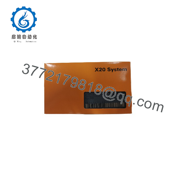
X20AO2622
X20AO2622
System Compatibility & Integration Requirements
| Item | Compatible component / requirement | Integration consideration |
|---|---|---|
| I/O platform | B&R X20 system | Designed for the X20 I/O architecture |
| Bus module | X20BM11 | 24 VDC keyed bus module |
| Bus module | X20BM15 | 24 VDC keyed bus module with node-number switch |
| Terminal block | X20TB06 | Six-pin terminal block |
| Terminal block | X20TB12 | Twelve-pin terminal block |
| Engineering configuration | B&R Automation Studio | Use the appropriate hardware configuration package |
| Output configuration | Voltage or current | Select the corresponding terminal connections |
| Hardware revision | J0 or later | Supports the specified 600 Ω current-output load |
Integration requirements
- Install the module with a compatible X20 bus module.
- Order the terminal block separately.
- Configure the output channel according to the required voltage or current signal.
- Check the receiving device’s input impedance and electrical reference.
- Confirm the hardware revision before applying the 600 Ω current-load specification.
- Do not assume channel-to-channel galvanic isolation.
Dimensions, Mounting & Connection Notes
The X20AO2622 uses the modular mounting arrangement of the B&R X20 I/O system.
| Installation parameter | Specification |
|---|---|
| Module pitch | 12.5 mm |
| Mounting orientation | Horizontal or vertical |
| Protection rating | IP20 |
| Terminal block | X20TB06 or X20TB12 |
| Bus module | X20BM11 or X20BM15 |
| Operating temperature, horizontal | -25 to +60°C |
| Operating temperature, vertical | -25 to +50°C |
| Storage temperature | -40 to +85°C |
| Relative humidity | 5–95%, non-condensing |
Installation considerations
- Disconnect the relevant power sources before replacing or installing the module.
- Check the X20 bus-module arrangement.
- Verify the terminal block and field wiring configuration.
- Select the appropriate voltage or current output connections.
- Confirm that the connected load falls within the specified operating limits.
- Check channel configuration and diagnostic status after commissioning.
The module has an IP20 protection rating. Its installation environment must therefore provide appropriate protection against dust and moisture exposure.
FAQ
1. What is the B&R X20AO2622?
The B&R X20AO2622 is a two-channel analog output module designed for the X20 I/O system. It converts digital control values into voltage or current signals.
2. How many analog output channels does X20AO2622 have?
It provides two analog output channels. Each channel can be configured for voltage or current operation.
3. Which output signal ranges does X20AO2622 support?
The module supports ±10 V, 0–20 mA, and 4–20 mA output signals through different terminal connections.
4. What is the digital converter resolution?
The digital converter resolution is 13 bits, including the sign bit. Voltage and current output use different digital representations.
5. Which terminal blocks are suitable for X20AO2622?
The supported terminal blocks include X20TB06 and X20TB12. The terminal block must be ordered separately.
6. Which bus modules can be used with X20AO2622?
The listed bus modules are X20BM11 and X20BM15.
7. What is the maximum current-output load?
The maximum current-output load is 600 Ω for hardware revision J0 or later and 500 Ω for earlier hardware revisions.
8. Are the output channels electrically isolated?
No. The two output channels are not isolated from each other. The module does provide 500 V RMS isolation between the channels and the bus.



