WhatsApp: +86 16626708626
 Email:
 Phone: +86 16626708626
Description
Core Product Summary (Brand / Model / Key Attributes)
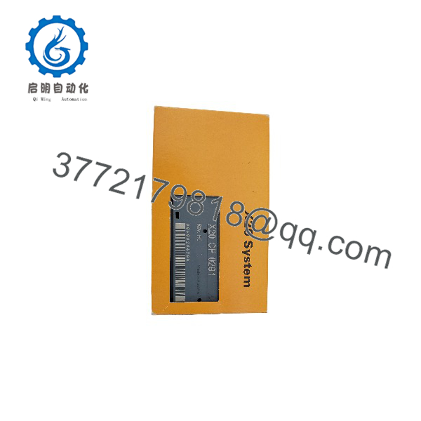
The B&R X20CP0291 is a compact CPU module from the B&R X20 automation system family. Functioning as a standalone PLC CPU or distributed controller node, this compact CPU module processes control program logic and coordinates real-time data exchange across connected I/O slices and fieldbus communication networks.
This module features 100 kB of SRAM for user application program data and 1 MB of integrated FlashPROM for program memory and system storage. Onboard communication interfaces include an RS232 serial interface, a CAN bus interface, and a 100Base-T Ethernet port (10/100 Mbit/s). Designed as an integrated compact unit, it attaches to an X20 base module, managing the X2X Link backplane for local I/O expansion while interfacing with upper-level network architectures.
Key Technical Specifications
| Parameter | Technical Specification |
| Brand & Order Number | B&R X20CP0291 |
| Product Type | Compact CPU / Logic Controller Module |
| System Family | B&R X20 System |
| User Memory (SRAM) | 100 kB |
| System Memory (FlashPROM) | 1 MB |
| Onboard Network Interfaces | 1x 100Base-T Ethernet (10/100 Mbit/s, RJ45) |
| Onboard Fieldbus Interfaces | 1x CAN bus interface |
| Onboard Serial Interfaces | 1x RS232 serial port |
| Backplane Bus Interface | X2X Link backplane communication master |
| Status Indicators | Diagnostics LEDs for CPU status, fieldbus link, and I/O bus activity |
| Degree of Protection | IP20 |
| Operating Temperature Range | -25°C to +60°C (horizontal), -25°C to +50°C (vertical) |
| Certifications / Approvals | CE, UKCA, cULus |
Detailed Product Overview
The B&R X20CP0291 acts as the central processing unit for standalone control setups or localized sub-system nodes within the modular B&R X20 automation platform. Engineered for compact control cabinet layouts, it combines processing power, memory storage, and multiple communication ports within a space-saving slice design.
Equipped with 100 kB of high-speed SRAM and 1 MB of non-volatile FlashPROM memory, the CPU manages real-time program execution, process variable handling, and system parameters. The integrated 100Base-T Ethernet port provides standard network connectivity for programming via B&R Automation Studio, human-machine interface (HMI) integration, and plant network data routing.
For fieldbus and peripheral communication, the controller includes an onboard CAN bus port alongside an RS232 serial connection. The CAN bus interface allows direct integration with field sensors, decentralized drives, or auxiliary sub-networks. Simultaneously, the CPU drives the internal X2X Link backplane bus, allowing high-speed deterministic cycle synchronization across directly attached X20 I/O modules.
X20CP0291
Engineering Selection Highlights
- Multi-Interface Compact Form Factor: Integrates Ethernet, CAN bus, and RS232 connectivity directly on a single compact CPU housing.
- Embedded Real-Time Execution: Manages deterministic cyclic tasks and I/O scanning via the high-speed X2X Link backplane master interface.
- Integrated Storage Memory: Features 100 kB SRAM and 1 MB FlashPROM for application code, system variables, and operational data logging.
- Seamless Software Integration: Configured, programmed, and diagnosed directly within the B&R Automation Studio engineering platform.
- Modular Mounting Architecture: Snaps onto standard X20 base modules, matching the footprint and DIN-rail mounting scheme of the entire X20 series.
System Compatibility & Integration Requirements
| Item / Dependency | Verified Compatibility or Requirement | Practical Note |
| System Family | B&R X20 System | Controls local X2X Link I/O backplane |
| Required Base Module | X20 Compact CPU Base Module | Serves as mounting base and terminal interlock carrier |
| Programming Tool | B&R Automation Studio | Required for application software design, CPU parameter setup, and debugging |
| Power Supply Requirement | Supplied via integrated base module / X20 power supply | Delivers internal system voltage for CPU and local X2X backplane |
| Terminal Connection | Standard X20 Terminal Blocks | Used for wiring power and serial/CAN communication lines |
Dimensions, Mounting & Connection Notes
- Mounting Method: Mounts directly onto an X20 CPU base module attached to a standard 35 mm DIN rail (EN 60715).
- Enclosure Rating: IP20 ingress protection, designed for installation in closed electrical control cabinets.
- Ethernet Connection: Front-accessible RJ45 socket for standard 10/100 Mbit/s network cables.
- Field & Power Wiring: Connected via removable push-in or screw terminal blocks attached to the matching base module.
- Operating Thermal Limits: Supports an ambient operating temperature range from -25°C up to +60°C in horizontal mounting orientation, with derating to +50°C in vertical orientation.
FAQ
What is the B&R X20CP0291?
The B&R X20CP0291 is a compact CPU module for the B&R X20 automation system, functioning as a programmable logic controller (PLC) with embedded communication interfaces.
What memory capacities does the X20CP0291 offer?
The CPU is equipped with 100 kB of SRAM user memory and 1 MB of FlashPROM program/system memory.
What communication interfaces are integrated on the X20CP0291?
The module features one 100Base-T Ethernet port (RJ45), one CAN bus interface, and one RS232 serial interface onboard.
Which programming environment is required for this CPU?
The X20CP0291 is programmed, configured, and maintained using B&R Automation Studio software.
What base components are needed to mount the X20CP0291?
The module requires a compatible X20 compact CPU base module and associated terminal blocks for mounting on a DIN rail and completing field wiring connections.
Verification & Troubleshooting Notes
- Status LED Inspection: Check front-panel LEDs for diagnostic indicators. A green LED indicates normal CPU execution, while red or flashing error LEDs signify configuration mismatch, program halt, or bus communication errors.
- Ethernet Link Verification: Confirm physical cable connection on the 100Base-T RJ45 port. Verify that IP address settings in Automation Studio match the target subnet.
- X2X Link Backplane Diagnostic: If attached I/O modules fail to communicate, verify that the base power supply module provides clean internal power and that module bus contacts are free of contamination.
- CAN Bus Termination: Ensure proper line termination resistors (120 Ω) are installed at both physical end nodes of the CAN bus network to prevent communication reflection errors.