
 WhatsApp: +86 16626708626
 Email:
  Phone: +86 16626708626
Description
Key Technical Specifications
| Parameter | X20CP1584 Specification |
|---|---|
| Manufacturer | B&R Industrial Automation |
| Controller family | X20 |
| Processor | Intel Atom, 0.6 GHz |
| RAM | 256 MB DDR2-SDRAM |
| User SRAM | 1 MB |
| Application storage | Removable CompactFlash |
| Ethernet | 10/100/1000BASE-T |
| RS232 | 1 interface |
| POWERLINK | 1 interface, V1/V2 |
| USB | 2 interfaces |
| X2X Link | 1 interface |
| Interface-module slots | 1 |
| Cooling | Fanless |
| Internal I/O power consumption | 0.6 W |
| Controller power consumption | 8.6 W, excluding interface module and USB |
| X2X Link supply consumption | 1.42 W |
| Weight | 400 g |
| Protection | IP20 |
| Redundancy | No controller redundancy |
B&R specifies the X20CP1584 as an Atom 600 MHz controller with 256 MB DDR2 memory. The unit combines Gigabit Ethernet, POWERLINK, USB, CompactFlash application storage, and an X20 interface-module slot.
Product Introduction
The B&R X20CP1584 is a central controller for the X20 PLC and distributed I/O platform. Its 0.6 GHz Intel Atom processor, 256 MB DDR2-SDRAM, removable CompactFlash storage, Ethernet, POWERLINK, USB, and X2X Link interfaces allow it to operate as the control processor in machine and industrial automation systems.
For maintenance and migration work, the important point is that this is more than a CPU-only replacement. The installed CompactFlash application memory, Automation Studio hardware configuration, interface-module selection, firmware/hardware revision, and POWERLINK/X2X topology must all be considered before replacing an existing controller.
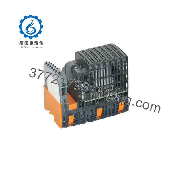
X20CP1584
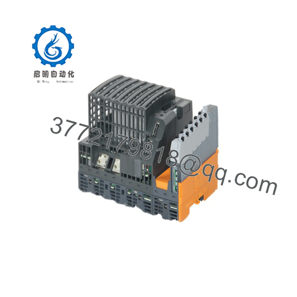
X20CP1584
Installation & Configuration Guide
Stage 1 — Pre-Installation Preparation (~5 minutes)
- Apply the site’s lockout/tagout procedure before removing the controller.
- Record the existing controller model, hardware revision, and status LEDs.
- Back up the current Automation Studio project.
- Photograph the existing wiring and module arrangement.
- Record Ethernet and POWERLINK configuration parameters.
- Check the CompactFlash card and application-memory arrangement.
- Prepare an ESD wrist strap, PH1 screwdriver, multimeter, wire labels, and documentation.
⚠️ Do not assume that a controller with the same basic model number contains the same application configuration. Preserve the original CompactFlash/application data and project backup until commissioning is complete.
Stage 2 — Removing the Existing Controller (~5 minutes)
- Confirm that the control system is safely de-energized.
- Label connected wiring and communication cables.
- Disconnect the relevant interfaces without pulling on the cable.
- Release the X20 mechanical locking mechanism.
- Remove the controller straight from the mounting arrangement.
- Inspect the backplane and adjacent X20 modules for contamination or damaged contacts.
- Keep the removed controller available until the replacement passes functional testing.
Stage 3 — Installing the X20CP1584 (~5 minutes)
- Wear ESD protection when handling the controller.
- Verify the replacement marking is X20CP1584.
- Check the CompactFlash/application-memory arrangement against the machine backup.
- Position the controller correctly on the X20 system.
- Engage the mechanical locking mechanism.
- Reconnect Ethernet, POWERLINK, USB, RS232, and X2X Link connections as applicable.
- Confirm that the X20 terminal block and end-cover arrangement are correctly installed.
B&R specifies the X20TB12 12-pin, 24 VDC keyed terminal block as part of the supplied hardware and lists specific CompactFlash cards as mandatory accessories.
Stage 4 — Power-On & Testing (~10–15 minutes)
- Use a multimeter to verify supply wiring before energizing the controller.
- Power the X20 system.
- Check the CPU, Ethernet, POWERLINK, CompactFlash, and battery indicators.
- Connect using the appropriate B&R engineering environment.
- Verify the controller hardware configuration.
- Confirm the installed firmware/hardware revision is appropriate for the project.
- Check Ethernet and POWERLINK communication.
- Verify X2X Link I/O communication.
- Perform a controlled I/O test before returning the machine to automatic operation.
- Save the final diagnostic status and configuration for maintenance records.
B&R currently provides Automation Studio hardware upgrades for the X20CP1584, including V3.0 and V4.0 upgrade packages. The manufacturer page also lists the X20 System User’s Manual and current documentation downloads.
Frequently Asked Questions (FAQ)
Is the a PLC CPU?
Yes. B&R classifies the as an X20 controller. It contains the CPU, memory, application-memory interface, Ethernet, POWERLINK, USB, RS232, X2X Link, and one expansion slot for an X20 interface module.
What processor does the use?
The controller uses an Intel Atom processor running at 0.6 GHz and includes 256 MB DDR2-SDRAM. B&R also specifies 1 MB of SRAM for the controller.
Does have Ethernet?
Yes. The controller has one onboard Ethernet interface supporting 10/100/1000BASE-T. It also has a separate POWERLINK interface for real-time automation networking.
Does the support CompactFlash?
Yes. CompactFlash is used as removable application memory. B&R lists several supported CompactFlash cards, including 512 MB, 1 GB, 2 GB, 4 GB, 8 GB, and 16 GB extended-temperature options.
Can I replace an existing X20 controller directly with an ?
Not automatically. The mechanical installation may be straightforward, but the engineering configuration must be checked. Verify the Automation Studio project, hardware configuration, firmware/hardware revision, CompactFlash contents, interface module, Ethernet parameters, POWERLINK configuration, and X2X Link topology before declaring the replacement equivalent.
Is controller redundancy available on the ?
B&R specifically lists Controller redundancy: No for this model. Do not substitute it into an application that requires redundant controller architecture without verifying the system design.
What should procurement verify before ordering an ?
At minimum, verify the exact material number, hardware revision, physical condition, CompactFlash requirement, included terminal block, and compatibility with the installed Automation Studio project. For a used or surplus unit, request photographs of the identification label and connectors and verify the unit’s functional test status before installation.



