WhatsApp: +86 16626708626
 Email:
 Phone: +86 16626708626
Description
Core Product Summary (Brand / Model / Key Attributes)
The B&R X20DI9371 is a high-density 12-channel digital input slice module designed for integration within the modular B&R X20 I/O system control architecture. Functioning as a sinking (NPN) digital input unit, the module captures 24 VDC logic signals from sensors, switches, proximity detectors, and digital field devices across industrial manufacturing networks.
Designed for 1-wire connection setups, this module packs 12 input points into a single compact slice footprint. Each channel accepts a 24 VDC nominal input signal (-15% / +20%) with a typical input current of 3.75 mA per point. Signal conditioning includes a fast hardware filter (≤100 µs) combined with a module-level software filter that defaults to 1 ms and is configurable up to 25 ms. The module operates with a low bus power consumption of 0.18 W and provides 500 Vrms galvanic isolation between the channels and the internal system backplane.
Key Technical Specifications
| Specification Parameter | Technical Detail |
| Product Model | X20DI9371 |
| Product Type | Digital input module |
| System Family | B&R X20 System |
| Number of Inputs | 12 channels |
| Input Circuit / Type | Sink (Sinking / NPN input logic) |
| Wiring Topology | 1-wire connection scheme |
| Nominal Input Voltage | 24 VDC (-15% / +20%) |
| Input Characteristic | Type 1 per EN 61131-2 |
| Typical Input Current | 3.75 mA at 24 VDC |
| Input Resistance | 6.4 kΩ (typical) |
| Switching Thresholds | Low state: < 5 VDC | High state: > 15 VDC |
| Hardware Filter | ≤ 100 µs |
| Software Filter | Default 1 ms (configurable from 0 to 25 ms in 0.2 ms steps) |
| Isolation Voltage | 500 Vrms (channel to bus) |
| Bus Power Consumption | 0.18 W |
| Internal I/O Power Consumption | 1.75 W |
| Operating Temperature | -25°C to +60°C (Horizontal) / -25°C to +50°C (Vertical) |
Detailed Product Overview
The B&R X20DI9371 operates as a compact digital interface module in control cabinet architectures utilizing the B&R X20 automation platform. Its primary function is acquiring 24 VDC discrete signals from field-mounted control elements—such as pushbuttons, limit switches, optical sensors, and pressure switches—and converting them into digital data registers for processing by the system master CPU.
Featuring 12 sinking input channels arranged in a 1-wire wiring configuration, the module reduces field cabling complexity by routing signal lines directly to individual terminals while utilizing common supply points. To maintain high immunity against electrical interference and contact bounce in harsh industrial environments, the module combines a fast hardware input filter (≤100 µs) with an adjustable software filter. The software filter applies to the entire module and can be tailored in Automation Studio software between 0 ms and 25 ms to match sensor response rates.
Mounting onto standard X20 bus modules allows the unit to connect seamlessly to backplane communication and I/O power supply lines. Built-in optical LEDs provide instant status indication for each channel, assisting in line setup and field troubleshooting. Galvanic isolation of 500 Vrms between the input circuits and the backplane bus preserves signal integrity and protects central control electronics from field-side voltage transients.
Engineering Selection Highlights
- 12-Channel Sinking Density: Integrates 12 digital inputs into a single X20 slice footprint, maximizing usable rack space in dense control panels.
- Configurable Dual-Stage Filtering: Features fixed hardware noise filtering (≤100 µs) along with software-adjustable filtering (0 to 25 ms) to eliminate signal chatter.
- 1-Wire Wiring Convenience: Optimized for 1-wire field cabling configurations to streamline terminal block wiring and panel assembly time.
- EN 61131-2 Type 1 Compliance: Accepts standard 24 VDC industrial sensor signals with defined switching levels (<5 VDC for Low, >15 VDC for High).
- High Galvanic Isolation: 500 Vrms isolation rating between input channels and backplane bus protects backplane electronics from field-side electrical disturbances.
- Low Power Dissipation: Consumes just 0.18 W from the internal backplane bus, helping manage overall cabinet thermal loads.
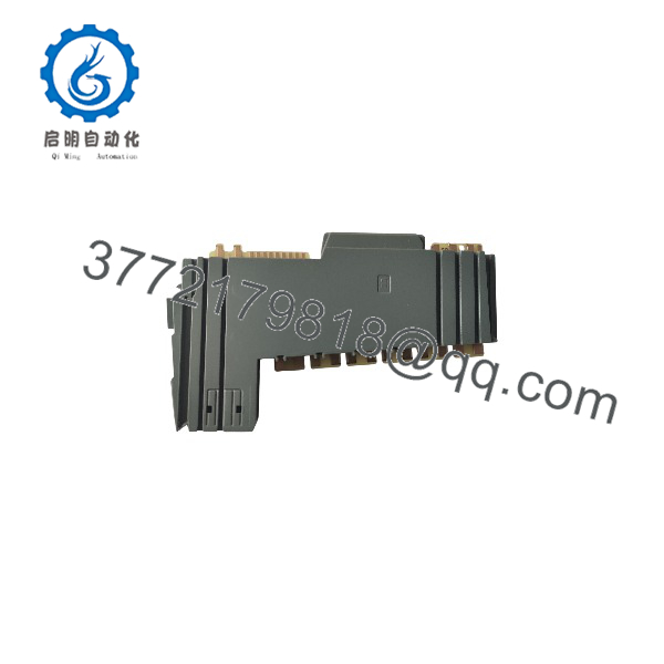
X20DI9371
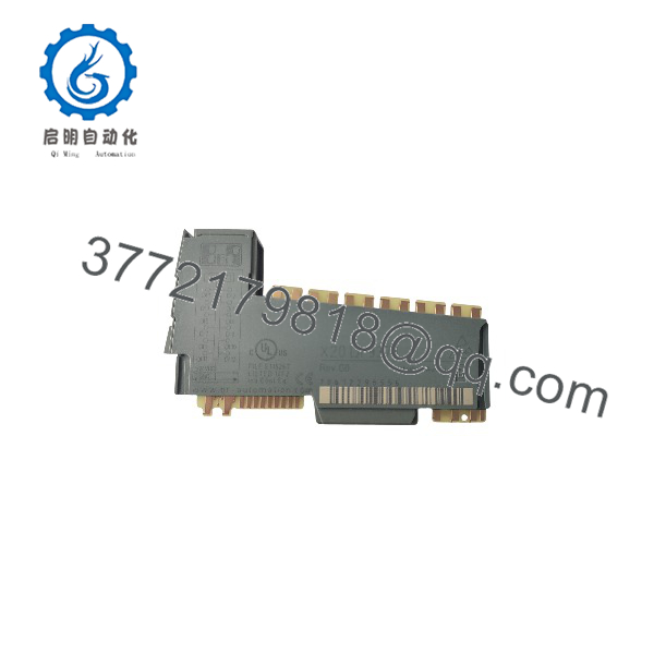
X20DI9371
System Compatibility & Integration Requirements
| Item / Dependency | Verified Compatibility or Requirement | Practical Note |
| System Architecture | B&R X20 System | Connects as a standard digital input slice module. |
| Bus Module Compatibility | X20BM11, X20BM15 | Required for backplane bus communication and I/O power pass-through. |
| Terminal Block Requirement | X20TB12 (12-pin terminal block) | Provides physical terminal connections for the 12 input signal channels. |
| Engineering Environment | B&R Automation Studio | Configured via Automation Studio hardware catalog upgrade files. |
| Approval Scope | cULus, CE, ATEX (Zone 2, Ex nA nC IIA T5 Gc), DNV, ABS, KC | Certified for general industrial, maritime, and hazardous location use. |
Dimensions, Mounting & Connection Notes
- Mounting Method: Modular plug-in slice design; attaches onto standard X20 DIN rail bus modules.
- Wiring Scheme: 1-wire connections; dedicated input signal line per channel connected to terminal block X20TB12.
- Operating Temperature Bounds: -25°C to +60°C in horizontal mounting orientation; -25°C to +50°C when mounted vertically.
- Altitude Derating: Suitable for operation from 0 to 2000 m without derating. Above 2000 m, reduce ambient operating temperature by 0.5°C per 100 m.
- Storage / Transport Limits: -40°C to +85°C ambient temperature range with 5% to 95% non-condensing relative humidity.
- Ingress Protection: IP20 rated enclosure according to EN 60529 standards.
FAQ
What is the B&R X20DI9371?
The B&R X20DI9371 is a 12-channel digital input slice module designed for the modular B&R X20 I/O control platform.
What input circuit type does the X20DI9371 use?
The module features sinking (NPN) input circuitry operating at 24 VDC nominal voltage.
What filter options are available on the X20DI9371?
It includes an integrated hardware filter (≤100 µs) and a software filter that defaults to 1 ms, configurable from 0 ms to 25 ms in 0.2 ms steps.
Which terminal block and bus module are required for installation?
The module mounts onto X20BM11 or X20BM15 bus modules and connects to field devices using the 12-pin X20TB12 terminal block.
What are the voltage switching thresholds for the input channels?
The module recognizes input signals under 5 VDC as a Low state and signals above 15 VDC as a High state.
Is the X20DI9371 approved for hazardous or marine locations?
Yes, it holds ATEX Zone 2 compliance (II 3G Ex nA nC IIA T5 Gc), cULus hazardous location approvals, and marine certifications from DNV and ABS.
How does mounting orientation affect the operating temperature rating?
The module is rated for -25°C to +60°C when mounted horizontally, and -25°C to +50°C when mounted in a vertical orientation.
Verification & Troubleshooting Notes
- Status LED Inspection: Check individual channel LED indicators on the front face of the module to verify physical input switching states during field testing.
- Input Voltage Level Verification: Measure voltage across input signal lines to ensure signal levels exceed 15 VDC for ON states and drop below 5 VDC for OFF states.
- Software Filter Tuning: If input signals experience contact bounce or high-frequency noise interference, adjust the software filter setting in Automation Studio toward higher values (up to 25 ms).
- Bus & Base Seat Check: If channel communications fail or diagnostic faults appear, verify that the module slice is fully seated into its X20BM11/X20BM15 bus module and that terminal block keying aligns properly.