WhatsApp: +86 16626708626
 Email:
 Phone: +86 16626708626
Description
Core Product Summary (Brand / Model / Key Attributes)
The B&R X20DOF322 is a high-density 16-channel digital output module designed for the B&R X20 I/O system control architecture. Functioning as a standard high-side (source) digital output slice, the module directs 24 VDC control signals directly to field actuators, relays, indicator lights, and solenoids in industrial automation applications.
This module features 16 output channels optimized for 1-wire connection setups, allowing compact installation within dense control cabinets. Each channel supplies up to 0.5 A nominal output current at 24 VDC nominal operating voltage. Channel outputs include integrated protection against overcurrent and short circuits via thermal shutdown mechanisms, along with built-in freewheeling diodes to suppress voltage spikes when switching inductive loads. Status monitoring with a 10 ms diagnostic delay ensures reliable channel verification across the network backplane.
Key Technical Specifications
| Specification Parameter | Technical Detail |
| Product Model | X20DOF322 |
| Product Type | Digital output module |
| System Family | B&R X20 System |
| Number of Outputs | 16 channels |
| Output Type | Source (High-Side switching) |
| Wiring Connection | 1-wire connection scheme |
| Nominal Output Voltage | 24 VDC |
| Nominal Output Current | 0.5 A per channel |
| Short-Circuit / Overload Protection | Integrated thermal cutoff on overcurrent or short circuit |
| Inductive Load Protection | Integrated internal freewheeling diodes |
| Diagnostic Status Monitoring | Output monitoring with 10 ms delay |
| Operating Temperature Range | -25°C to +60°C (derating above +55°C) |
| Thermal Derating | Max. 0.35 A total current per channel above +55°C |
Detailed Product Overview
The B&R X20DOF322 serves as a high-density digital output interface within the modular X20 control architecture. In complex automation machinery, it operates as an output slice module that converts internal logic state instructions into high-side 24 VDC switching signals for downstream field equipment. By organizing 16 output circuits into a single slice footprint, the module optimizes cabinet spatial requirements while delivering solid-state switching capacity for solenoid valves, control relays, indicator panels, and actuator coils.
Each of the 16 outputs is designed for source (p-switching) operation, supplying up to 0.5 A at 24 VDC per channel under standard operating conditions. To prevent damage from field faults, the module incorporates comprehensive electronic protection. Overcurrent and short-circuit conditions trigger an automatic thermal cutoff, preserving internal semiconductor integrity. Built-in inverse freewheeling diodes protect the switching circuitry against inductive kickback generated by coils and relay windings during turn-off phases.
System integration within the X20 backplane occurs through compatible X20 bus modules and terminal blocks. Diagnostic data and channel switching states map into B&R Automation Studio software environment using standardized register data points. When operating in environments with elevated ambient temperatures, the module maintains full performance up to +55°C before requiring thermal current derating.
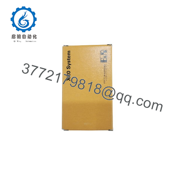
X20D0F322
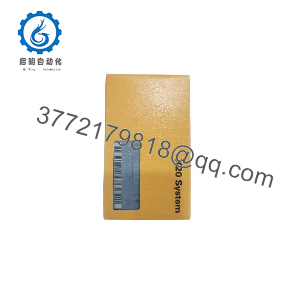
X20D0F322
Engineering Selection Highlights
- 16-Channel High Density: Packs 16 digital output points into a single X20 slice footprint, maximizing panel space efficiency.
- 24 VDC High-Side Sourcing: Delivers 0.5 A nominal current per channel using source (PNP) output logic compatible with standard industrial actuators.
- 1-Wire Connection Design: Simplifies field wiring architecture when utilizing common supply and ground distribution networks.
- Integrated Inductive Protection: Internal freewheeling suppression diodes absorb inductive back-EMF, eliminating the need for external suppressor elements on standard coils.
- Thermal Fault Recovery: Built-in overcurrent and short-circuit protection automatically safeguards individual output transistors during field wiring faults.
- Defined Thermal Operating Window: Operates at full nominal output ratings up to +55°C ambient, with clear derating rules extending up to +60°C environments.
System Compatibility & Integration Requirements
| Item / Dependency | Verified Compatibility or Requirement | Practical Note |
| System Architecture | B&R X20 System | Mounts as a standard I/O slice module. |
| Bus Module Requirement | Compatible X20 bus modules (e.g., X20BM11, X20BM15) | Required for backplane power and communication coupling. |
| Terminal Block Fit | 12-pin X20 terminal block (e.g., X20TB12) | Standard spring-clamp or screw terminal block options. |
| Engineering Environment | B&R Automation Studio | Configurable using standard I/O mapping registers and data points. |
| Network Cycle Sync | Fixed output update offset (<60 µs) | Output states synchronize with the network cycle (SyncOut). |
Dimensions, Mounting & Connection Notes
- Mounting Style: Plug-in slice module designed for installation on standard DIN rail backplane base modules within the X20 I/O system.
- Wiring Topology: 1-wire connection scheme; channels connect directly to dedicated output terminals while external loads share common return paths.
- Thermal Clearances: Standard vertical enclosure installation requires unblocked air channels above and below the module rack.
- Operating Temperature Bounds: Standard operating range spans -25°C to +60°C. Output current limits transition to 0.35 A per channel when operating between +55°C and +60°C ambient.
- Inductive Switching Limits: High-frequency switching of large inductive loads may require external freewheeling diodes if cycle rates exceed internal thermal dissipation limits.
FAQ
What is the B&R X20DOF322?
The B&R X20DOF322 is a 16-channel digital output module belonging to the modular B&R X20 automation and I/O system.
What type of output switching does the X20DOF322 use?
The module uses source (high-side) digital output switching rated for 24 VDC nominal voltage.
What is the maximum current rating per output channel?
Each output channel supports a nominal switching current of up to 0.5 A at 24 VDC under standard operating temperatures.
How are field devices wired to the X20DOF322?
The module uses a 1-wire connection structure, pairing signal lines with shared external ground return connections.
Does the module require external protection for inductive loads?
No, the module features integrated internal freewheeling diodes designed to absorb voltage spikes from standard inductive loads like relays and solenoids.
What thermal derating applies to the X20DOF322?
No current derating is needed up to +55°C ambient temperature. Between +55°C and +60°C, total maximum output current per channel is reduced to 0.35 A.
Which bus modules are required to install the X20DOF322?
The module installs using compatible X20 bus modules such as the X20BM11 or X20BM15 alongside a 12-pin terminal block (e.g., X20TB12).
Verification & Troubleshooting Notes
- Channel LED Status: Monitor front-panel orange I/O status LEDs to visually verify channel output switching states during operational execution.
- Overcurrent / Short-Circuit Tripping: If an output channel shuts down unexpectedly, check field wiring for short circuits or load impedances that pull current beyond the 0.5 A limit. The internal thermal cutoff automatically disengages overloaded channels.
- High-Inductive Load Heating: High switching frequencies on heavily inductive loads can cause internal heating. Verify operating cycle frequency against inductive dissipation curves to determine if external inverse diodes are necessary.
- Voltage Supply Verification: Ensure 24 VDC system power is maintained within specified voltage limits across the bus module power contacts to prevent false diagnostic fault reporting.