
 WhatsApp: +86 16626708626
 Email:
  Phone: +86 16626708626
Description
Key Technical Specifications
- Part Number: AAP3798102-00031
- Manufacturer: Cameron
- Product Type: Main Logic Module (MLM)
- Controller Family: Cameron Vantage compressor control platform
- Primary Function: Main control/logic processing
- System Application: Industrial compressor control
- Associated Equipment: Cameron compressor control panels
- Module Role: Central logic/control board
- Replacement Reference: Bay Controls MLM replacement
- Related Part: AAP3798102-00037 is identified as a separate Cameron UIM part number, so it should not be confused with the AAP3798102-00031 MLM.
- Part Status: Legacy/discontinued replacement-market part; current availability varies by supplier.
- Weight: Approximately 5.16 lb according to Radwell’s listing.
Technical verification note: Public listings for this part number contain conflicting specifications. For example, some third-party listings incorrectly describe AAP3798102-00031 as an analog/digital I/O or generic processor module. The stronger cross-reference evidence identifies it specifically as the MLM/main logic module. Therefore, specifications such as supply voltage, CPU type, memory capacity, I/O channel count, and communication protocol should not be treated as verified without the original Cameron documentation or a clear photograph of the installed unit.
Product Introduction
The Cameron AAP3798102-00031 is a Main Logic Module (MLM) used in Cameron compressor control systems, particularly the Vantage controller platform. It functions as a central control-board assembly rather than a conventional PLC plug-in I/O module.
For replacement work, the complete part number matters. Do not substitute the nearby AAP3798102-00037 UIM part number; the two perform different roles. Because AAP3798102-00031 is a legacy component, verify board revision, connector arrangement, controller configuration, and existing firmware before installation.
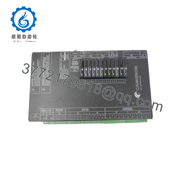
AAP3798102-00031
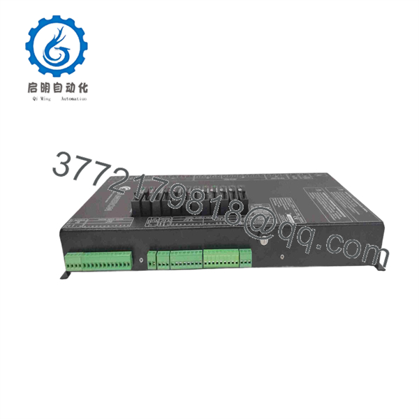
AAP3798102-00031
Installation & Configuration Guide
Stage 1: Pre-Installation Preparation — About 10 Minutes
⚠️ Safety First: Place the compressor in the approved shutdown state. Follow the plant’s lockout/tagout procedure and isolate the controller power before removing the MLM.
Tools Required:
- ESD wrist strap
- Phillips screwdriver
- Digital multimeter
- Wire labels
- Smartphone or camera
- Original system drawings/configuration documentation
Data Backup:
- Record the complete AAP3798102-00031 part number and any board revision visible on the label.
- Photograph the installed MLM from several angles.
- Photograph every connector before disconnecting it.
- Record controller configuration and alarm settings where applicable.
- Preserve the existing control-system configuration before hardware removal.
Stage 2: Removing the Old Module — About 5 Minutes
- Confirm that the compressor control system is in a safe shutdown condition.
- Isolate controller power.
- Wait for the power supply to discharge according to the equipment maintenance procedure.
- Label each connector before removal.
- Disconnect the cables without pulling on individual conductors.
- Release the board/module retaining hardware.
- Remove the MLM carefully and keep it in an ESD-safe location.
- Inspect connectors, sockets, and mounting hardware for contamination or mechanical damage.
⚠️ Keep the original board until commissioning is complete. If the replacement behaves differently, the original provides the reference for connector position, board revision, and configuration.
Stage 3: Installing the New Module — About 5 Minutes
- Establish ESD protection before handling the replacement board.
- Verify against the removed unit.
- Compare board labels, revision markings, connectors, and mounting arrangement.
- Install the MLM in the original position.
- Secure all retaining hardware.
- Reconnect each cable according to the photographs and wiring documentation.
- Confirm every connector is fully seated.
Self-Checklist:
- Part number matches
- Board revision checked
- Connector positions verified
- Configuration documented
- Retaining hardware secured
- ESD precautions maintained
Stage 4: Power-On & Testing — About 10-15 Minutes
- Perform a final visual inspection.
- Check for loose conductors, misplaced connectors, or damaged pins.
- Verify the controller power supply before energizing the system.
- Power the control system according to the Cameron maintenance procedure.
- Observe controller/module status indications.
- Verify that the MLM initializes correctly.
- Check communication between the controller and associated control-panel components.
- Confirm compressor permissives and interlocks remain correctly configured.
- Perform an approved dry-run sequence before returning the compressor to service.
- Monitor alarms and controller status during the initial operating period.
⚠️ Do not load an assumed configuration into the replacement board simply because the part number matches. Legacy compressor controllers can contain application-specific settings. Preserve the existing configuration and compare it before commissioning.
Troubleshooting Note: If the controller does not initialize, first check power, connector seating, board revision, and configuration compatibility. If the MLM powers up but the controller does not communicate correctly with the associated interface equipment, verify the system configuration before changing additional hardware.
Frequently Asked Questions (FAQ)
What is Cameron ?
It is a Main Logic Module (MLM) used in Cameron compressor control systems. Multiple independent sources identify specifically as the MLM, while AAP3798102-00037 is associated with the UIM.
Is a PLC I/O module?
No. It should not be treated as a conventional digital-input or analog-output module. The available cross-reference information identifies it as the main logic/control board of the compressor controller. Some reseller pages incorrectly classify it as generic I/O or processor hardware, so verify the original equipment documentation when engineering a replacement.
Is Cameron obsolete?
It appears to be a legacy part that is now primarily available through industrial replacement and surplus channels. Current listings offer unused, never-used, and refurbished conditions, so the condition must be confirmed for each individual unit.
Can be replaced directly by AAP3798102-00037?
No. These part numbers serve different functions. is identified as the MLM, while AAP3798102-00037 is identified as the UIM. Do not order the UIM as an MLM replacement.
Will replacing the MLM erase the compressor control configuration?
The hardware replacement itself should not be treated as a configuration migration. The important issue is whether the replacement MLM contains the correct application configuration and compatible firmware/revision. Back up and document the existing controller configuration before removing the original board.
What condition should I specify when purchasing ?
Specify the exact commercial condition you require: Factory New/Original, New Surplus, Never Used, or Refurbished/Tested. Radwell, for example, lists separate condition categories for this part, demonstrating why “new” should not be assumed from a generic product listing.
Are the published electrical specifications reliable for this part?
Not all of them. Public reseller pages provide contradictory values for voltage, processor, memory, I/O, and communications. Those figures should not be published as definitive specifications without Cameron documentation. For procurement and replacement engineering, the part number, MLM function, controller family, board revision, and physical connector arrangement are the safer verified identifiers.



