
 WhatsApp: +86 16626708626
 Email:
  Phone: +86 16626708626
Description
Key Technical Specifications
- Manufacturer: Cameron
- Part Number: AAP3798102-00130
- Alternate Description: Maestro Universal Display Control Module
- Product Category: HMI / MMI / OIT Operator Interface
- Application: Compressor monitoring, parameter entry, alarm display, and system diagnostics
- Platform: Maestro Generation 1 Universal Control System
- User Interface: LCD display with keypad input
- Operating System Platform: Windows CE-based controller environment
- Associated I/O Module: AAP3798102-00131 Maestro Universal I/O Control Module
- Replacement / Migration Reference: AAP37988102-00140 Maestro Generation 2 controller requires compatibility review before installation
- Configuration Compatibility: Reported compatible configuration files between Generation 1 AAP3798102-00130 and Generation 2 AAP37988102-00140; verify the installed application revision and site hardware before ordering
- Approximate Shipping Weight: 5 lb / 2.27 kg
- Lifecycle Status: Discontinued by manufacturer
- Installation Type: Panel-mounted display/control module; verify mounting cutout, connector arrangement, and harness condition against the removed unit
The AAP3798102-00130 is identified by multiple industrial-parts sources as a discontinued Cameron Maestro HMI/operator-interface module. Sources also identify its use as the Generation 1 Maestro display control unit and associate it with the AAP3798102-00131 I/O control module.
Product Introduction
The Cameron AAP3798102-00130 is a Maestro Generation 1 operator interface module used on compressor-control packages for local display, alarm review, parameter adjustment, and diagnostic access. It functions as the display-side control module within a Cameron/Ingersoll Rand Maestro Universal Control system, typically paired with the AAP3798102-00131 Universal I/O Control Module.
For a downtime-critical replacement, match the complete AAP3798102-00130 number—not merely “Maestro HMI.” This is a discontinued part, and visible similarity to the Generation 2 AAP37988102-00140 does not eliminate the need to verify firmware, saved configuration, harness connectors, and site-specific I/O configuration before commissioning.
Troubleshooting Quick Reference
| Symptom | Possible Cause | Relevance to this Part | Quick Check Method | Recommendation |
|---|---|---|---|---|
| No display and no keypad response | Missing DC supply, blown control fuse, damaged display module | ⚠️ Medium | Measure the specified DC supply at the module power connector using a Fluke 115 or equivalent; check the upstream fuse and common return before condemning the HMI | Confirm supply voltage under load first. Replace the HMI only if correct power and ground reach the unit but it remains dead |
| Display backlight is on but screen is blank | Failed LCD assembly, corrupted boot image, internal display connection fault | ✅ High | Cycle power after documenting alarm state; observe boot behavior; inspect screen for faint characters using a flashlight at an angle | If the module boots with no usable display, replacement is normally the practical field repair |
| Keypad presses do not register | Worn membrane keypad, liquid ingress, failed internal keypad circuit | ✅ High | Enter a noncritical menu and test each key one at a time; compare response to the site’s operating manual | Do not force keys or use solvents. Replace the interface if several keys fail consistently |
| “Communication Timeout” or lost-controller message | I/O controller offline, communication cable fault, firmware mismatch, address/configuration issue | ⚠️ Medium | Inspect the cable between the AAP3798102-00130 and AAP3798102-00131; verify controller LEDs; compare firmware and configuration records | Check the I/O module, communications wiring, and configuration before replacing the display module |
| Compressor starts but local values remain frozen | HMI communications fault, stale application data, controller scan issue | ⚠️ Medium | Compare local display values with independent gauges or supervisory data; power-cycle only under approved operating procedure | If the controller values update elsewhere, investigate the display module and its communication connection |
| Unit repeatedly resets during startup | Supply voltage sag, poor ground, failing internal power circuitry | ⚠️ Medium | Monitor the module supply during boot; look for voltage drop when relays, solenoids, or starter circuits energize | Correct the power-quality issue first. A replacement HMI will show the same fault if the supply collapses |
| New replacement powers up but will not communicate | Firmware revision mismatch, wrong configuration, DIP/jumper setting error, incompatible harness | ✅ High | Photograph the removed unit’s labels and switch settings; document firmware and load the approved configuration only | Request the correct hardware and firmware range before shipment; do not assume every Maestro-looking unit is plug-and-play |
| Screen is cracked, yellowed, or has dark areas | Physical damage, UV exposure, aging LCD/backlight | ✅ High | Inspect under power and verify whether alarm acknowledgment and navigation remain usable | Replace the HMI before it becomes a no-display event during an upset condition |
❗ Field warning: Do not wire this module from memory. Legacy Maestro revisions can look nearly identical while using different internal hardware, connector arrangements, or firmware behavior. Take clear photos of every connector, label, and switch setting before removing the old unit.
❗ Firmware warning: I have seen a controller swap turn into a two-day “Communication Timeout” chase because a site installed a different software revision without documenting the original. Record the old unit’s version and configuration before power-down whenever possible.
❗ ESD warning: Use a grounded wrist strap and handle the module only by its enclosure. Dry-weather static can damage display-control electronics before the unit ever reaches the panel.
If you are stuck, send technical support clear photos of the front label, rear connectors, controller LEDs, wiring harness, and all diagnostic messages. Include the old unit’s firmware/configuration information and a photo of the associated AAP3798102-00131 module if installed.
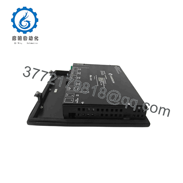
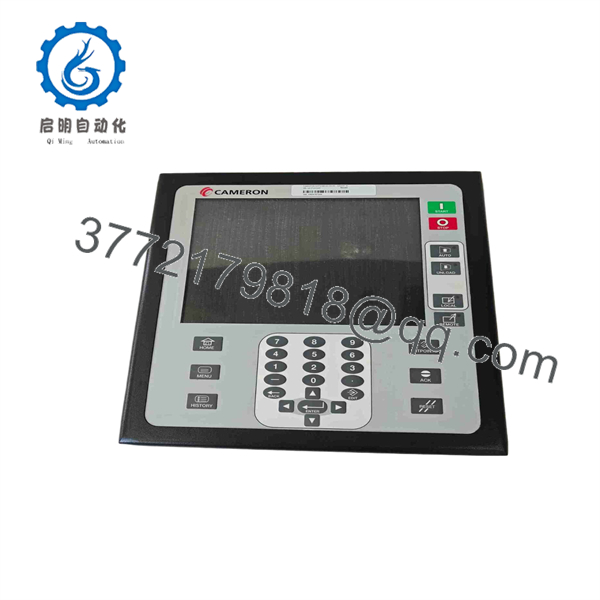
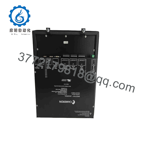
AAP3798102-00130
AAP3798102-00130
AAP3798102-00130
Frequently Asked Questions
Is the Cameron a PLC or an HMI?
It is primarily an HMI/MMI/operator-interface module, not a general rack PLC CPU. It provides the local display, keypad input, alarm visibility, parameter adjustment, and diagnostic interface for a Maestro compressor-control package. The associated AAP3798102-00131 module is commonly identified as the Universal I/O Control Module.
Can I replace with a newer AAP37988102-00140 module?
Possibly, but do not treat it as an automatic substitution. Available product information describes AAP37988102-00140 as a Generation 2 Maestro controller with newer electronics, while reporting common mounting dimensions and configuration-file compatibility with the Generation 1 . Verify firmware, connectors, exact application files, site wiring, and OEM approval before ordering.
Can I hot-swap the AAP3798102-00130?
No—plan for a controlled power-down unless the machine OEM’s written procedure explicitly permits otherwise. This is a legacy compressor-control interface, and pulling it energized can create communication faults, corrupt an active configuration, damage connectors, or expose electronics to ESD. Kill control power, lock out according to site procedure, and photograph the original setup before removal.
Will my programming and compressor settings remain after the swap?
Do not assume they will. Some settings may reside in the controller, some may be stored in the interface, and some may depend on the installed application version. Before replacement, capture the firmware revision, setpoints, calibration data, alarm history if required, DIP-switch positions, jumper positions, and any available configuration backup. If the old unit is still responsive, this documentation is worth far more than trying to reconstruct settings after a failure.
Why does the replacement unit need the exact part number?
“Maestro” is a platform name, not a complete compatibility statement. Similar-looking units may differ in generation, connector pinout, electronics, firmware support, display configuration, or the software expected by the paired I/O module. Match the full part number, suffix, labels, and hardware generation. The manufacturer has discontinued this unit, so verified part-number matching matters even more.
Is this item new surplus or refurbished?
Condition must be stated unit by unit. A New Original / New Surplus unit is unused legacy inventory that may have an older manufacturing date and may not include current OEM factory warranty. A Refurbished (tested) unit has previously been installed or handled and should be supplied only after documented functional testing. Marketplace listings show both new-surplus and refurbished availability, so request actual photos, condition confirmation, and the supplier’s written warranty before purchase.
What testing should a supplier perform before shipping a refurbished unit?
At minimum, request documented inbound inspection, serial-number and label photos, display and keypad verification, power-on/boot testing, communication handshake testing with a compatible Maestro setup, and a sustained operational run. Electrical checks should include ground continuity and insulation resistance where applicable. The supplier should seal the module in an ESD bag, use protective packing, and provide a dated QC record. Test photos and videos should be available upon request.



