WhatsApp: +86 16626708626
 Email:
 Phone: +86 16626708626
Description
Core Product Summary (Brand / Model / Key Attributes)
The Danaher Motion SAM-DA-400-07B-P4N-F (also designated as SAM-DA-400/480-07B-P4N-F) is a digital AC servo amplifier belonging to the Smart Axis Manager (SAM) drive series. Designed for industrial motion control applications within PAM and SAM automation systems, this unit operates on a 400 VAC to 480 VAC 3-phase mains supply, generating an output power rating in the 1.5 kW class to drive multi-phase AC brushless servomotors.
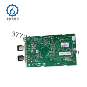
Equipped with a fiber optic EasyBus network interface featuring two ring communication ports, the SAM-DA-400-07B-P4N-F provides fast, noise-immune fieldbus data transfer and multi-axis command synchronization. The drive integrates a 24 VDC auxiliary power circuit, 10 digital user inputs, 8 transistor outputs, dual rotary node addressing switches, and an onboard single-character 7-segment LED display for immediate diagnostic feedback.
Key Technical Specifications
| Technical Parameter | Verified Specification |
| Product Type / Function | Digital AC Servo Amplifier / Drive |
| Product Family / Series | Danaher Motion SAM (Smart Axis Manager) Series |
| Operating Mains Voltage | 400 VAC to 480 VAC (3-Phase) |
| Nominal DC Bus Voltage | 565 VDC to 680 VDC |
| Nominal Output Power | Approximately 1.5 kW (Power Category 07B) |
| Auxiliary Control Power Input | 24 VDC (19.2 VDC undervoltage limit) |
| Fieldbus Network Communication | EasyBus Fiber Optic Ring Medium (2 ports) |
| Fieldbus Node Addressing | Dual Rotary Knob Address Switches |
| Onboard Digital I/O | 10 Digital Inputs / 8 Transistor Outputs (16-pin connector) |
| Motor Temperature Sensing | 2 Dedicated Motor Temperature Sensor Inputs |
| Local Status Display | Single-Character 7-Segment Display with Diagnostic LEDs |
Detailed Product Overview
The Danaher Motion SAM-DA-400-07B-P4N-F serves as a high-precision power conversion and motion execution module within centralized industrial automation networks. By converting incoming 400/480 VAC three-phase line power into controlled multi-phase AC output currents, the amplifier manages motor velocity, position, and torque tracking for high-duty-cycle automated machinery.
A key engineering feature of the SAM-DA-400-07B-P4N-F is its fiber optic EasyBus communication topology. Utilizing a two-port fiber ring interface, the drive isolates control signals from electromagnetic interference (EMI) commonly encountered in heavy industrial environments. The separate 24 VDC auxiliary power connection preserves internal control processor logic and diagnostic monitoring during mains power interruptions. Additionally, integrated user I/O terminals directly handle local machine signals such as hardware travel limit switches and interlocks, minimizing external I/O rack requirements.
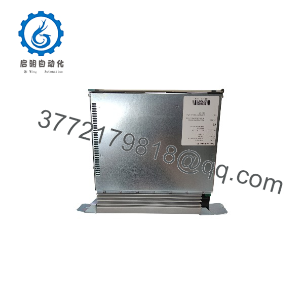
SAM-DA-400-07B-P4N-F
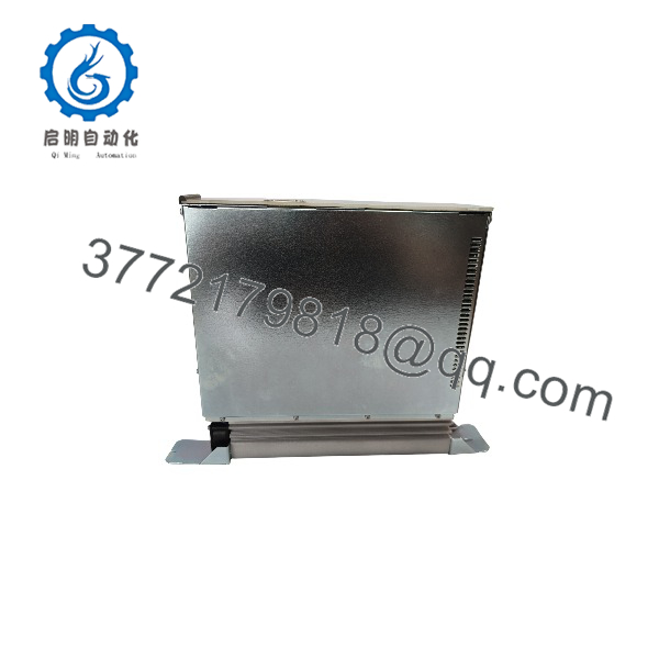
SAM-DA-400-07B-P4N-F
Engineering Selection Highlights
- Fiber Optic EasyBus Interface: Dual-port optical ring connectivity ensures high-speed, noise-immune fieldbus communications across synchronized motion axes.
- 400/480 VAC High-Voltage Design: Accepts global 3-phase high-voltage power mains, delivering an output power capacity of approximately 1.5 kW.
- Separate Auxiliary Logic Supply: Requires an independent 24 VDC auxiliary input, maintaining control intelligence, status feedback, and bus communication during main power isolation.
- Integrated Local Machine I/O: Provides 10 digital inputs and 8 transistor outputs directly on the module via a 16-pin interface for localized machine control.
- Hardware Addressing & Diagnostics: Features mechanical rotary switches for physical node address setting and a front-panel 7-segment display for clear operational status identification.
Dimensions, Mounting & Connection Notes
- Mounting Configuration: Panel-mount form factor designed for vertical mounting inside grounded, protective electrical cabinets.
- Network Interface: Two fiber optic ring ports for EasyBus network loop-through cabling.
- I/O Interface: 16-pin terminal plug handling 10 digital inputs and 8 transistor outputs with dedicated common pins.
- Power Terminations: Heavy-duty terminal connections for 3-phase AC line input, 24 VDC auxiliary logic supply, DC bus access, and 3-phase motor output leads.
- Node Setting Interface: Dual mechanical rotary switches located on the module faceplate for manual node ID assignment.
System Compatibility & Integration Requirements
| Item / Dependency | Verified Compatibility or Requirement | Practical Note |
| System Controller Architecture | Danaher PAM / SAM Motion Control Systems | Communicates via optical EasyBus network protocol |
| Mains AC Supply | 400 VAC to 480 VAC (3-phase) | Verify proper branch circuit fusing and input voltage rating |
| Auxiliary Power Supply | External regulated 24 VDC supply | Must maintain voltage above the 19.2 VDC undervoltage threshold |
| Network Medium | Fiber optic ring cabling | Requires clean fiber optic connections into the dual EasyBus ports |
| Motor Feedback & Thermal | Compatible AC servomotors with temperature sensors | Wire motor thermal protection directly to the 2 thermal input pins |
FAQ
What is the Danaher SAM-DA-400-07B-P4N-F?
It is a 400/480 VAC digital AC servo amplifier module from Danaher’s SAM (Smart Axis Manager) product series equipped with a fiber optic EasyBus network interface.
What power supply inputs does this model require?
The amplifier requires a 400–480 VAC 3-phase mains supply for motor power and a separate 24 VDC auxiliary supply for control electronics.
How does the SAM-DA-400-07B-P4N-F communicate with the system controller?
It communicates using a fiber optic ring medium via two dedicated EasyBus network ports on the module.
How many local I/O points are integrated into the unit?
The drive includes 10 digital user inputs and 8 transistor outputs connected through a 16-pin connector.
How is the network node address configured on this amplifier?
The node address is selected manually using two physical rotary knob switches on the front panel.
Verification & Troubleshooting Notes
- DC Bus High Voltage Hazard: Main power generates internal DC bus levels ranging from 565 VDC to 680 VDC. Always disconnect AC mains power and wait at least 5 minutes to allow internal bus capacitors to fully discharge before accessing terminals or handling wiring.
- Auxiliary Undervoltage Faults: If the unit fails to initialize or displays an undervoltage fault, check that the 24 VDC auxiliary control voltage remains strictly above the 19.2 VDC minimum operating threshold under load.
- Fiber Optic Network Diagnostics: Monitor the 7-segment display and status LEDs for EasyBus transmission errors. Clean optical connectors and inspect fiber patch cables for bending radius violations if network communication fails to synchronize.