
 WhatsApp: +86 16626708626
 Email:
  Phone: +86 16626708626
Description
Key Technical Specifications
| Parameter | Specification / Value |
| Manufacturer | DEIF A/S |
| Part Number | AL8-2 (e.g., Variant 01 / 2998760020 / 1043050060A) |
| Auxiliary Supply Voltage | 12 V DC / 24 V DC / 48 V DC / 110 V DC (Nominal; min. 10 V DC) |
| Power Consumption | Approx. 6 W |
| Alarm Channel Inputs | 8 Digital Inputs (Selectable N/O or N/C dry contact) |
| Relay Outputs | 3 Form-C Relays (1 x Horn/Audible, 2 x Assignable Output A & B) |
| Relay Contact Rating | AC: 250 V, 2 A, 400 W |
| Time Delay Adjustment | Programmable input delay (0 to 40 seconds) |
| Front Panel Interface | 8 Red Flashing Alarm LEDs, Power LED, First-Out Indication |
| Master/Slave Setup | Interconnects up to 5 units in centralized master/slave topology |
| Enclosure / Mount | DIN Q96 Standard Housing (92 x 92 mm panel cut-out) / IP54 Front |
| Operating Temperature | −10 to +55 °C (+14 to +131 °F) |
| Weight | Approx. 0.35 kg (0.77 lbs) |
Product Introduction & Supply Chain Strategy
The DEIF AL8-2 is a microprocessor-controlled 8-channel alarm panel engineered for critical fault monitoring in marine engine rooms, power generation plants, and industrial switchboards. Featuring eight individually programmable digital inputs, three relay outputs, and first-out alarm identification, the unit provides instant audible and visual status indication for parameter faults such as low oil pressure, high coolant temperature, or generator trip conditions.
Sourcing the DEIF AL8-2 as New Surplus gives plant maintenance managers and marine superintendents a secure, high-reliability replacement without relying on worn, harvested hardware. Sourcing factory-fresh surplus stock guarantees unaged internal electrolytic capacitors and pristine relay contact surfaces. Keeping a ready-to-deploy AL8-2 on-site prevents vessel detentions and costly generator shutdown delays, reducing overall Total Cost of Ownership (TCO).
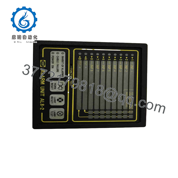
AL8-2
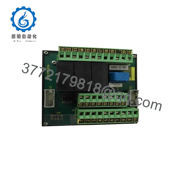
AL8-2
Installation & Configuration Guide
1.Pre-Installation & Safety Isolation:Disconnect auxiliary power and prepare panel cut-out.
- Lock out and tag out all auxiliary control power feeds to the switchboard cabinet.
- Put on an ESD grounded wrist strap to prevent static discharge to the rear terminal connections and internal board logic.
- Verify that the cutout matches the standard Q96 DIN format (92 x 92 mm).
2.Panel Mounting & Front Alignment:
- Insert the AL8-2 unit through the front cutout of the panel door.
- Slide the included side mounting clamps into place and tighten the retaining screws evenly to secure the IP54 front gasket seal.
- Ensure adequate clearance behind the rear terminal block for wire harness routing.
3.Terminal Wiring & Output Assignment:
- Wire the 8 dry-contact alarm inputs to their respective channel terminals according to panel engineering drawings.
- Connect the horn output relay to the external acoustic siren/beacon, and assign Relays A and B to external shutdown or PLC trip loops.
- Connect the auxiliary DC power supply leads to the designated power terminals, ensuring correct polarity.
4.Power-On & Onboard Push-Button Programming:
- Apply power and confirm that the green “POWER ON” LED lights steadily.
- Use the front-panel CHANNEL SELECT, FUNCTION SELECT, and ENTER keys to configure each channel’s input contact logic (N/O vs. N/C), delay times, and relay trigger assignments.
- Perform a simulated input fault and press “LAMP RESET” to verify first-out LED logic and horn silencing functionality.
Firmware/Software Versions & Upgrade Notes
- Push-Button Configuration: The AL8-2 requires no external software programming cables or computer software. All input logic (N/O or N/C), time delays, cable supervision, and output assignments are programmed directly via three front-panel push buttons.
- Master/Slave Configuration: When interconnecting multiple units (up to 5 panels), remove the jumper plug on port X2 of the designated Master unit. Upon fault detection on any Slave unit, the central horn output activates while group outputs A and B remain local to the triggering card.
- Replacement Jumper Check: Always document the channel parameters of the old panel before removal so the replacement unit can be programmed identically prior to returning the machinery to active service.
Frequently Asked Questions (FAQ)
Is this DEIF alarm panel genuine OEM and completely new?
Yes, this unit is New Surplus (Original New). It is unissued, unused factory-original DEIF inventory sourced from canceled vessel projects or system integration overstock. It has never been installed in an active marine switchboard or industrial cabinet.
Why choose New Surplus over a cheaper refurbished unit?
Refurbished alarm panels from marine vessels often suffer from salt-air corrosion, vibration-stressed solder joints, and degraded relay contacts. In critical power applications, a failed alarm relay can allow an engine overheat condition to go undetected, resulting in catastrophic engine failure. Buying New Surplus ensures factory-fresh component life and 100% operational reliability.
Can I set individual channels for different contact types (N/O vs. N/C)?
Yes. Each of the 8 alarm channels can be individually programmed via the front panel to accept normally open (N/O) or normally closed (N/C) dry contacts, as well as customized time delays from 0 to 40 seconds.
What does “First-Out” indication mean on the ?
In the event of multiple rapid fault conditions, the identifies which fault occurred first by flashing the corresponding LED faster or ahead of subsequent channel LEDs. This allows engineers to pinpoint the primary root cause of a trip.
What warranty is provided with this surplus product?
We back this unit with a 1-Year Comprehensive Replacement Warranty. Every DEIF panel undergoes visual inspection, power-rail validation, and terminal relay functional testing prior to dispatch.



