
 WhatsApp: +86 16626708626
 Email:
  Phone: +86 16626708626
Description
3. Key Technical Specifications
| Parameter | Value |
|---|---|
| Supply voltage | 12…24 V DC −25 %/+30 % (9…31.2 V); load-dump protected per IEC 7637-2 |
| Output voltage | 0…±10 V DC, output impedance 500 Ω |
| Output current | 0…±20 mA DC, R load max. 500 Ω |
| Integrating time | 2.5…25 s or 12.5…125 s (selectable) |
| PWM output | 0…6 V DC, 500 Hz ±50 Hz |
| PWM resolution | 10,000 steps (>13 bit) |
| Response time | <0.1 s |
| Operating temperature | −25…+70 °C (operating); −10…+55 °C (nominal) |
| Housing / cut-out | 96 × 96 mm front; 92 × 92 mm cut-out |
| Protection | IP52 (front), IP20 (rear) |
| Inputs (preset/up/down) | 9…31.2 V DC, mutually galvanically isolated |
| Status / Auto relays | Max. 30 V AC/DC, 50 mA |
| Weight (approx.) | 0.3 kg |
4. Product Introduction
The DEIF EPQ96-2 is a digitally controlled electronic potentiometer that replaces conventional motor potentiometers for electronic speed governor control on diesel generators and industrial engines. It converts relay outputs from a PI controller or synchronizer into a precise voltage, current, or PWM signal while supporting J1939 CAN input for direct interface with modern engine controllers.
Engineers select the EPQ96-2 for its maintenance-free design (no moving parts), dual integrating-time ranges that mimic variable gearboxes, and the ability to retain or preset the last output value after a power interruption. The unit mounts in a standard Q96 panel cut-out and provides both analog (±10 V / ±20 mA) and dual PWM outputs, making it a direct drop-in for many Caterpillar and DEIF-compatible governor systems.
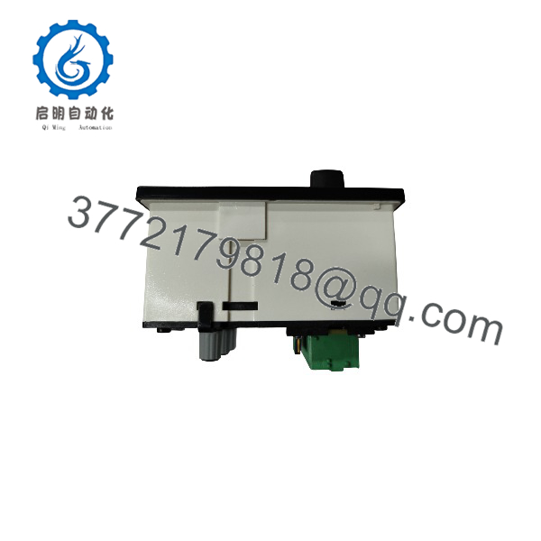
EPQ96-2
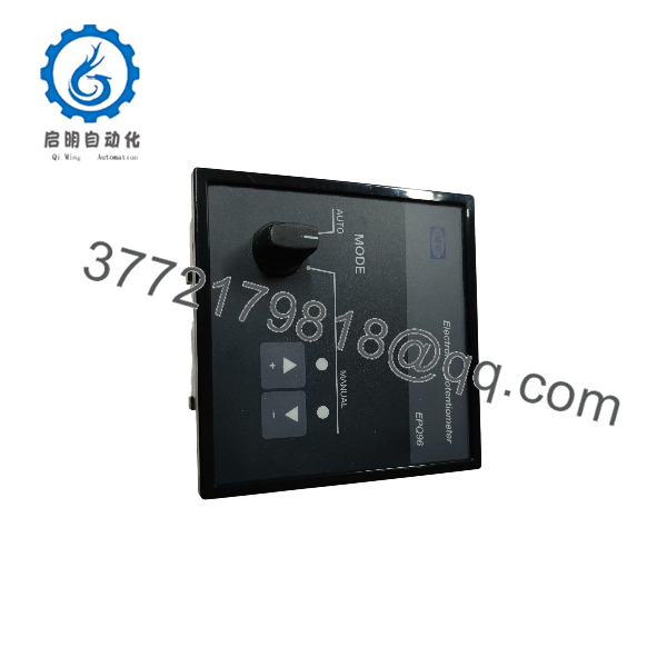
EPQ96-2
5. Troubleshooting Quick Reference
| Symptom | Possible Cause | Relevance to this Part | Quick Check Method | Recommendation |
|---|---|---|---|---|
| No green power LED | Supply voltage missing or out of range | ✅ High | Measure 9–31.2 V DC at supply terminals | Verify PSU and fuses first |
| Green LED flashing 1 Hz | Internal fault or self-test failure | ✅ High | Confirm supply stable; check status relay contact | Unit likely needs replacement |
| Output stuck at zero / no ramp | Up/Down or Preset inputs not active | ✅ Medium | Apply 18–32 V DC to Up or Down input; watch LED | Confirm wiring and input voltage |
| Output jumps on power restore | “Last value” vs “Preset” switch setting | ✅ High | Check rear switch position and pot settings | Set switch and pots to match site requirement |
| CAN LED never flashes | No J1939 traffic or termination issue | ✅ Medium | Verify CAN H/L wiring and 120 Ω termination | Check AGC or master controller output |
| PWM duty incorrect | “PWM duty” pot misadjusted | ✅ Medium | Measure PWM with scope; adjust rear pot | Re-commission droop setting |
| Auto relay never closes | Unit left in Manual mode | ❌ Low | Press Auto button; confirm yellow Auto LED | Switch to Auto mode |
If symptoms persist after these checks, capture photos of the front LEDs, rear switch positions, and a short video of the power-up sequence, then contact technical support with the diagnostic logs.
6. Frequently Asked Questions (FAQ)
Q: Can I hot-swap the EPQ96-2 while the generator is running?
A: No. Remove power first. The unit has an internal relay that disconnects the active electronics on supply loss, but live insertion risks backplane or governor transients. Kill the 12/24 V supply, swap the module, then restore power.
Q: Does the EPQ96-2 keep its last output value after a power failure?
A: Yes, if the rear switch is set to “Last.” The unit stores the value in memory and reloads it on power-up. If set to “Preset,” it returns to the value set by the rear potentiometer. After any power cycle the unit always boots into Auto mode.
Q: Is this a direct replacement for older DEIF EP-Q96 or motor potentiometers?
A: In most cases yes. The EPQ96-2 adds J1939 and dual PWM outputs while keeping the same 96 × 96 mm form factor and core analog ranges. Always verify the integrating-time range and output polarity against the existing governor datasheet before final wiring.
Q: Why is the price lower than a factory-new unit from DEIF?
A: These units are New Original / New Surplus stock. They are unused, factory-sealed or warehouse-stored OEM product with full traceability. They have not been installed or refurbished. Warranty is 1 year from shipment.
Q: How do I set the integrating time and min/max limits?
A: Use the rear switch for the ×1 (2.5–25 s) or ×5 (12.5–125 s) range, then adjust the “Time,” “Min,” and “Max” potentiometers. The slope stays constant regardless of span; narrowing the span simply shortens the ramp time proportionally. Document the final pot positions with a photo before closing the panel.
Q: Does the unit support both voltage and current output at the same time?
A: The single analog output is either voltage or current depending on the jumper between terminals 11 and 12. The two PWM outputs are always available and independent of the analog selection.
Q: What firmware or configuration tools are required?
A: None. All settings are hardware potentiometers and switches. No software or firmware update is needed for standard operation.



