
 WhatsApp: +86 16626708626
 Email:
  Phone: +86 16626708626
Description
Key Technical Specifications
| Parameter | Value |
|---|---|
| Manufacturer | DEIF |
| Product | IOM 230 |
| Product Family | IOM 200 |
| Module Type | CAN bus analog interface |
| Communication | CAN bus |
| Analog Outputs | 2 |
| Governor Output | GOV, terminals 7–8 |
| AVR Output | AVR, terminals 9–10 |
| GOV/AVR Current Output | 0–20 mA / ±25 mA |
| GOV/AVR Voltage Output | 0–10 V DC / ±12 V DC |
| P Load-Sharing Output | Terminal 14 |
| Q Load-Sharing Output | Terminal 12 |
| P/Q Load-Sharing Range | −5 to 0 to +5 V DC |
| Supply Terminals | 1–2, +12/24 V DC and 0 V DC |
| CAN Terminals | 4 CAN-H, 5 CAN-GND, 6 CAN-L |
| PC Interface | TTL interface via service port |
| Status Indication | Green = system OK; Red = system failure |
| CAN Address | Selectable by DIP switch |
| Maximum IOM 230 Units | Up to 2 in certain ASC 150 applications |
DEIF specifies the IOM 230 as an analog interface module with two analog outputs plus P and Q load-sharing outputs. Output type and range are selected through DIP switches, while voltage outputs can be adjusted using potentiometers.
Product Introduction
The DEIF IOM 230 is a CAN bus analog interface module for DEIF genset and power-management controllers. It provides two configurable analog outputs for governor and AVR control and adds analog P/Q load-sharing interfaces for applicable systems. DEIF documents compatibility with controllers including the AGC-4 Mk II, AGC 150, ASC 150, and AGC 200.
The module is useful where the controller requires additional analog regulation outputs or analog load-sharing signals. The GOV and AVR channels support current and voltage signal formats, while the IOM 230’s additional P/Q interface operates from −5 to +5 V DC.
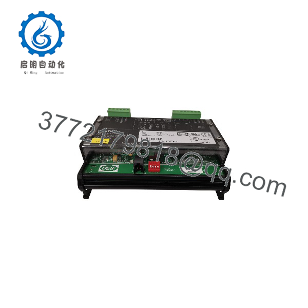
IOM 230
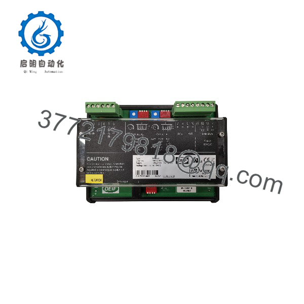
IOM 230
Installation & Configuration Guide
Stage 1: Pre-Installation Preparation — Approximately 5–10 Minutes
⚠️ Safety First: Put the generator or power system into the approved maintenance state. Follow the site’s lockout/tagout procedure before disconnecting the IOM 230.
Tools Required:
- ESD wrist strap
- Small screwdriver
- Digital multimeter
- Wire labels
- Smartphone or camera
- DEIF controller documentation
Before removal:
- Record the exact IOM 230 identification.
- Photograph the terminal wiring.
- Record the IOM CAN ID.
- Photograph the GOV and AVR output-selector DIP switches.
- Record the connected controller model and firmware/application version.
- Document whether the P/Q load-sharing terminals are wired.
Stage 2: Removing the Existing Module — Approximately 5 Minutes
- Confirm the generator/control system is in the approved shutdown state.
- Isolate power according to the applicable DEIF installation procedure.
- Label each connected conductor.
- Disconnect the CAN bus and power connections.
- Disconnect GOV, AVR, and P/Q load-sharing wiring as applicable.
- Release the module from its mounting arrangement.
- Remove the IOM 230 carefully.
⚠️ Do not rely on wire color alone. The DEIF documentation identifies specific terminal functions, including CAN-H at terminal 4, CAN-GND at 5, and CAN-L at 6.
Stage 3: Installing the New IOM 230 — Approximately 5–10 Minutes
- Confirm the replacement is an IOM 230, not an IOM 220.
- Install the module in the correct mounting position.
- Reconnect the DC supply:
- Terminal 1: +12/24 V DC
- Terminal 2: 0 V DC
- Reconnect CAN:
- Terminal 4: CAN-H
- Terminal 5: CAN-GND
- Terminal 6: CAN-L
- Reconnect GOV:
- Terminal 7: GOV output
- Terminal 8: GOV common
- Reconnect AVR:
- Terminal 9: AVR output
- Terminal 10: AVR common
- Reconnect P/Q load-sharing wiring where required.
- Match the original CAN ID and output-selector settings.
DEIF specifies that the CAN cable shield should not be connected to ground; it should be connected only to the designated GND terminals.
Output selector check:
| Output | Switch 1 | Switch 2 | Switch 3 |
|---|---|---|---|
| ±25 mA | ON | OFF | OFF |
| 0–20 mA | OFF | ON | OFF |
| ±12 V DC | ON | OFF | ON |
| 0–10 V DC | OFF | ON | ON |
Switches 1 and 2 must not be set to the same position.
Stage 4: Power-On & Commissioning — Approximately 10–15 Minutes
- Verify all wiring before energizing the controller.
- Apply control power.
- Check the IOM 230 status LED.
- Check the CAN status LED.
- Confirm the controller detects the IOM 230.
- Verify the configured CAN ID.
- Check the GOV analog output.
- Check the AVR analog output.
- If used, verify P and Q load-sharing signals.
- Confirm the generator responds correctly before returning it to automatic operation.
DEIF documents ID0, ID1, and ID2 selections for the IOM 230. In the documented configuration, ID0 participates in load-sharing functionality, while ID1 and ID2 can be used for additional PID output assignments.
Frequently Asked Questions (FAQ)
What is the DEIF IOM 230 used for?
The IOM 230 expands the analog-output capability of compatible DEIF controllers. Its two analog outputs can be used for governor, AVR, or general-purpose PID control, and the module also provides analog P/Q load-sharing outputs.
What is the difference between IOM 220 and IOM 230?
Both provide two analog outputs for control applications. The IOM 230 adds the analog P and Q load-sharing interface, which is the main functional distinction documented by DEIF.
Which DEIF controllers support the IOM 230?
DEIF documentation lists the AGC-4 Mk II, AGC 150, ASC 150, and AGC 200 among controllers that communicate with the IOM 200 series through CAN bus. Specific application limits depend on the controller and software version.
What output signals can the IOM 230 provide?
The GOV and AVR outputs can be configured for 0–20 mA, ±25 mA, 0–10 V DC, or ±12 V DC. The voltage output ranges are adjustable. The P/Q load-sharing interface uses a −5 to +5 V DC range.
Can I use multiple IOM 230 modules?
Yes, but the permitted quantity depends on the controller and application. For example, DEIF’s ASC 150 documentation states that up to two IOM 230 modules can provide four additional analog outputs. Other DEIF software documentation describes configurations using multiple IOM 220/230 units for PID outputs, so the exact controller/software combination should be checked before installation.
How is the IOM 230 address configured?
The CAN ID is selected through the module’s DIP switches. DEIF documents ID0, ID1, and ID2 selections, with ID0 used for load-sharing functionality. Different IOMs on the same CAN network require appropriate addressing.
Can I replace an IOM 230 without checking the controller software?
That is not a good assumption. The hardware communicates through CAN bus, and DEIF controller software determines how the analog outputs are assigned. For example, DEIF documents IOM 220/230 outputs as selectable PID outputs in applicable AGC software. Verify the controller’s application software and parameter configuration before commissioning a replacement.



