WhatsApp: +86 16626708626
 Email:
 Phone: +86 16626708626
Description
Key Technical Specifications
| Parameter | Specification |
|---|---|
| Manufacturer | DEIF |
| Model | MTR-4-215 |
| Item number | 1200510022 |
| Product category | Programmable multi-transducer |
| Network compatibility | Single-phase and three-phase AC networks |
| Measurement functions | AC voltage, current, power, power factor, frequency, energy, THD, and demand |
| Maximum voltage input capability | Up to 1,000 V line-to-line, subject to configuration and installation requirements |
| Accuracy class | 0.5 or 0.3, depending on the applicable configuration |
| Analog outputs | 2 |
| Output configuration | Individually programmable |
| Output characteristic | Up to five breakpoints |
| Communication interface | RS-485 |
| Communication protocol | Modbus |
| Response time | Less than 50 ms |
| Auxiliary supply | 19–300 V DC / 40–276 V AC |
| Configuration interface | USB 2.0 |
| Display | Not identified as a display instrument in the manufacturer’s product description |
| Intended integration | PLCs and analog instrumentation |
| Marine applications | Designed for electrical networks requiring applicable marine approval |
The voltage capability, accuracy class, and response time are published for the MTR-4 product family. Confirm the specific measurement configuration, input wiring, current-transformer ratios, and applicable approvals before commissioning.
Main Features and Advantages
Two Configurable Analog Outputs
The MTR-4-215 provides two analog outputs that can be assigned to selected electrical parameters. This can reduce the number of separate transducers required when a control system needs multiple analog measurements.
RS-485 Modbus Integration
The communication interface allows the transducer to exchange measurement data with compatible PLCs, supervisory systems, and other Modbus-capable equipment. Confirm the communication settings and register map against the applicable DEIF documentation before integration.
Broad Electrical Measurement Coverage
The MTR-4 platform measures and calculates more than 50 parameters, including voltage, current, power, frequency, energy, power factor, and THD. The parameters available at each output depend on the selected configuration.
Fast Response
DEIF specifies a response time below 50 ms for the MTR-4 family. This supports electrical monitoring applications that need timely measurement updates, although the transducer should not be treated as a substitute for a dedicated protection relay.
Flexible Auxiliary Power
The published auxiliary supply range is 19–300 V DC or 40–276 V AC. Verify the permitted supply conditions and installation requirements for the exact unit before applying power.
Application Fields
- Marine power systems: Electrical measurement and monitoring on vessels and marine installations.
- Generator monitoring: Measurement of generator voltage, current, frequency, and power.
- Power management systems: Providing electrical data to supervisory controllers.
- Industrial switchboards: Monitoring single-phase and three-phase AC networks.
- PLC and DCS integration: Supplying selected electrical measurements through analog outputs or Modbus.
- Energy monitoring: Collecting power, energy, power-factor, and harmonic-distortion data where configured.
The manufacturer identifies the MTR-4 family for single-phase and three-phase networks and applications involving PLCs, analog instruments, and marine electrical systems.
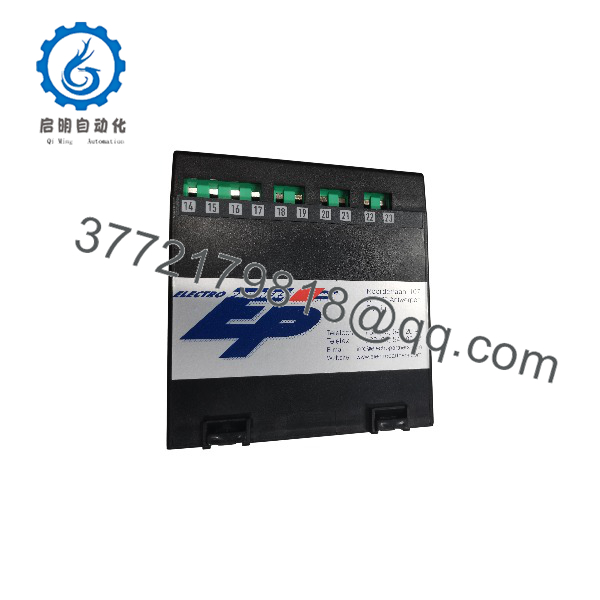
MTR-4-215
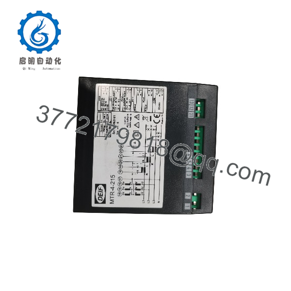
MTR-4-215
Installation and Configuration Guide
Stage 1: Pre-Installation Preparation
Estimated time: 10–20 minutes
- Notify operations and obtain authorization to work on the electrical measurement circuit.
- Follow the site’s isolation and lockout/tagout procedures. Verify the circuit is safe before disconnecting any conductors.
- Record the existing voltage-input and current-transformer wiring, including phase assignments and CT polarity.
- Photograph the auxiliary power connections, analog outputs, and RS-485 communication terminals.
- Confirm the model number and item number on the replacement unit.
- Prepare the applicable DEIF installation instructions, wiring diagrams, and configuration software.
Tools: Suitable multimeter, insulated screwdrivers, conductor labels, wiring diagrams, and the appropriate USB configuration interface.
Stage 2: Remove the Existing Unit
Estimated time: 5–10 minutes
- Confirm that the associated monitoring and control functions are in the approved maintenance state.
- Isolate the measurement circuit as required by the installation procedure.
- Label each conductor before disconnecting it.
- Disconnect voltage inputs, current inputs, auxiliary power, analog outputs, and communication wiring as applicable.
- Remove the unit using the specified mounting procedure and inspect the surrounding wiring and terminals.
Critical safety warning: Never open-circuit an energized current-transformer secondary. Follow the approved CT shorting and isolation procedure before disconnecting current-input wiring.
Stage 3: Install the Replacement
Estimated time: 10–20 minutes
- Verify that the replacement is a DEIF MTR-4-215.
- Install the unit using the mounting instructions applicable to the hardware revision.
- Reconnect voltage and current inputs according to the approved wiring diagram.
- Verify phase sequence, CT polarity, and configured transformer ratios.
- Reconnect auxiliary power, analog outputs, and RS-485 communication wiring.
- Confirm that communication polarity, bus termination, and addressing follow the installation design.
Checklist:
Stage 4: Configuration and Commissioning
Estimated time: 10–30 minutes, depending on the installation
- Restore power after completing the required electrical safety checks.
- Connect the USB configuration interface and use the appropriate DEIF configuration software.
- Verify the measurement settings, output assignments, and scaling.
- Confirm the Modbus address and communication parameters against the receiving controller’s configuration.
- Compare measured voltage, current, frequency, and power against an appropriate reference instrument.
- Test both analog outputs across the expected operating range.
- Read the configured parameters over Modbus and confirm that the receiving PLC or supervisory system interprets them correctly.
- Document the final configuration and obtain operations approval before returning the system to service.
Troubleshooting notes
- Incorrect power readings: Check phase sequence, voltage connections, CT polarity, and transformer ratios.
- No Modbus communication: Verify RS-485 wiring, address, baud rate, parity, and the correct register map.
- Incorrect analog output: Check output assignment, scaling, wiring, and the receiving analog-input configuration.
- Unexpected readings after replacement: Compare the replacement’s configuration with the recorded settings rather than assuming the original configuration has been retained.
Consult the DEIF MTR-4 product documentation for the relevant installation instructions, datasheet, and configuration software.
Frequently Asked Questions
Q1. What is the difference between DEIF MTR-4-215 and MTR-4-315?
The MTR-4-215 has two analog outputs and RS-485 Modbus communication. The MTR-4-315 has three analog outputs and RS-485 Modbus. If a replacement changes the number of outputs, verify the wiring, output assignments, and control-system configuration before installation.
Q2. Does the MTR-4-215 support Modbus RTU?
The manufacturer specifies RS-485 Modbus communication. Confirm the exact protocol mode, serial settings, and register mapping in the applicable product documentation before configuring the host controller.
Q3. Can the MTR-4-215 measure three-phase electrical power?
Yes. The MTR-4 family is designed for single-phase and three-phase AC network measurement. The voltage connections, current-transformer arrangement, and selected network configuration must match the actual installation.
Q4. How many analog outputs does the MTR-4-215 provide?
It provides two individually configurable analog outputs. The parameters and output characteristics should be configured for the receiving equipment’s requirements.
Q5. Can be replaced by an -015?
Not as a direct functional replacement when analog outputs are required. The MTR-4-015 has no analog outputs, although it supports RS-485 Modbus. Check the complete application requirements before considering this variant.
Q6. Is the DEIF MTR-4-215 available as new original stock?
Availability and condition depend on the supplier’s inventory. Request photographs of the actual unit and identification label, along with a written condition statement. Confirm whether the item is factory sealed, new surplus, or refurbished and tested. Do not assume that a listing marked “new” establishes the unit’s provenance.
Q7. What should I verify before purchasing?
Confirm the complete model number, DEIF item number 1200510022, number of analog outputs, RS-485 Modbus requirements, electrical input configuration, auxiliary supply, condition, warranty, and dispatch lead time. For marine applications, verify that the unit’s approval documentation satisfies the requirements of the vessel, classification society, and installation.