
 WhatsApp: +86 16626708626
 Email:
  Phone: +86 16626708626
Description
Key Technical Specifications
| Parameter | Value |
|---|---|
| Manufacturer | Delta Tau Data Systems; later Omron motion-control product family |
| Model | ACC-24E2 |
| Full Board Reference | 3Ax-603397-xUxx family reference |
| Product Type | UMAC axis expansion / digital servo interface board |
| Controller Compatibility | UMAC, UMAC Turbo, Ultralite, and MACRO Station controllers through UBUS |
| Rack Format | Industrial 3U rack system |
| Standard Axis Capacity | 2 servo channels on the base board |
| Maximum Axis Capacity | 4 servo channels with ACC-24E2 Option 1D piggyback board |
| UMAC System Capacity | Up to 8 ACC-24E2x boards; up to 32 additional servo-interface channels |
| MACRO Station Capacity | Up to 2 cards for 8 channels; MACRO 16-Axis CPU supports up to 4 cards |
| Servo Interface | PMAC2-style direct PWM servo circuitry |
| Output Modes | Three PWM top-and-bottom pairs or pulse-and-direction per channel |
| Encoder Feedback | Differential or single-ended A/B quadrature with index pulse |
| Flag Inputs | Nine input flags per channel |
| Flag Outputs | Two output flags per channel |
| Current Feedback | Interface for two external serial ADCs, 8 to 18 bits, per channel |
| Position Compare Output | Fast CMOS driver; specified firing within 100 ns of programmed position |
| Position Compare Driver | DS75451N; 5 V, 10 mA maximum, totem-pole CMOS, 5 MHz maximum |
| Base-Board Power | +5 V DC at 700 mA |
| Option 1D Power | +5 V DC at 200 mA |
| Flag Circuit Supply | 12–24 V DC typical; 0–5 V DC supported with correct resistor-pack configuration |
| Encoder Inputs | TTL-level; configurable for differential or single-ended operation |
| Encoder-Loss Detection | Supported for differential incremental encoders with required resistor-pack configuration |
| Connector Options | Phoenix Contact terminal blocks or optional 15-pin AMP D-sub encoder/compare connectors |
| Base Card Slot Use | One 3U rack slot |
| Four-Axis Configuration | Two rack slots with Option 1D piggyback board installed |
| Lifecycle Status | Legacy/obsolete motion-control accessory; verify supply and exact hardware revision before ordering |
The ACC-24E2 is a UMAC-family axis expansion card that provides PMAC2-style direct PWM servo-interface circuitry. The base board supports two channels, while the optional Option 1D expansion provides channels three and four; it interfaces with UMAC or MACRO Station CPUs through the high-speed UBUS expansion bus.
Product Introduction
The Delta Tau ACC-24E2 is a UMAC motion-control axis expansion board for direct digital PWM servo amplifiers and pulse-and-direction motion interfaces. It installs in an industrial 3U UMAC rack and connects to UMAC, UMAC Turbo, Ultralite, or MACRO Station controllers through UBUS. The base card provides two motion channels, with an Option 1D piggyback board expanding the assembly to four channels.
Unlike the ACC-24E2A analog ±10 V variant, the ACC-24E2 provides direct PWM phase-voltage command outputs. It is intended for systems using compatible digital PWM servo drives, TTL encoder feedback, limits, home switches, user flags, and amplifier-fault signals. Match the exact ACC-24E2 suffix, connector style, jumper configuration, controller type, and installed firmware before ordering.
Troubleshooting Quick Reference
| Symptom | Possible Cause | Relevance to this Part | Quick Check Method | Recommendation |
|---|---|---|---|---|
| Green D17 Power Good LED is off | Missing +5 V backplane supply, unseated card, failed rack PSU, internal board fault | ⚠️ Medium | Measure +5 V DC at the UMAC rack backplane; inspect card seating and edge connector; confirm the supply remains stable under load | Check the rack PSU and backplane before replacing the . The base card requires approximately 700 mA from +5 V DC |
| No axis motion but controller runs | Servo amplifier disabled, output mode incorrect, PWM wiring error, interlock active | ⚠️ Medium | Check amber amplifier-enable LEDs D5 and D6; verify amplifier enable circuit, drive interlocks, and U/V/W/T command wiring | Compare the output-mode settings and wiring against the drive manual before replacing the card |
| Axis commands motion in the wrong direction | Encoder polarity reversed, motor-phase wiring issue, incorrect PMAC encoder-decode setting | ❌ Low | Jog at low speed under safe conditions; verify A/A̅ and B/B̅ encoder pairs; review the applicable I7mn0 encoder-decode setting | Correct feedback polarity or software configuration. Do not reverse motor wiring blindly |
| Following error occurs immediately after enable | Lost encoder feedback, incorrect encoder wiring, encoder supply issue, servo tuning error | ⚠️ Medium | Verify green Encoder 1/2 Power OK LEDs D10 and D11; measure encoder 5 V supply; inspect A, A̅, B, B̅, C, and C̅ signals | Check feedback and tuning first. A failed is possible, but bad encoder cables are more common |
| Encoder counts remain at zero | Disconnected encoder, incorrect differential/single-ended resistor-pack configuration, damaged input circuit | ✅ High | Verify encoder supply and signal transitions with an oscilloscope; inspect TB1/TB2 or J1/J2 wiring; compare resistor-pack orientation with the application | Confirm encoder type and wiring. Replace the board only after known-good encoder signals reach the input connector |
| Random position jumps or intermittent following errors | Cable shielding problem, poor grounding, loose terminal block, electrical noise, failing encoder | ⚠️ Medium | Tug-test terminal conductors with power off; inspect shield termination; trend position feedback while moving cables | Correct cable and grounding issues first. Use differential encoder wiring for long or noisy runs |
| Axis has PWM output but drive shows a phase-fault input | Incorrect E10/E11 fault polarity jumper, amplifier fault wiring mismatch, drive fault active | ❌ Low | Check amplifier fault outputs at the PWM connector; compare high-true/low-true fault logic with E10/E11 jumper position | Match the card’s fault-input polarity to the amplifier documentation; default jumper position is low-true |
| Stepper drive will not move | E1A–E1D or E2A–E2D jumpers not set for pulse-and-direction, wrong software output mode | ❌ Low | Inspect channel jumpers and verify pulse/direction output at the connector with an oscilloscope | The ships configured for direct PWM. Install the required jumpers only for pulse-and-direction applications |
| Multiple axes fault after adding a replacement board | Duplicate S1 address, clock-source conflict, UBUS configuration error | ✅ High | Compare S1 DIP-switch settings with all installed boards; verify only one timing source is configured where required | Set a unique address before powering up. Duplicate addresses can create confusing multi-axis faults |
| Watchdog or timing faults after card replacement | E13 clock jumper incorrect, incompatible Turbo firmware behavior, card address order changed | ✅ High | Check E13 and installed UMAC Turbo firmware; for firmware 1.937 or later, verify auto-configuration jumper arrangement | Document the old board’s E13 setting. The clock configuration is one of the easiest ways to create a system-wide motion fault |
| Board works cold but faults after extended operation | Cabinet temperature, poor 5 V supply regulation, aging components, vibration-related connector issue | ⚠️ Medium | Monitor +5 V DC at the backplane and cabinet temperature during operation; inspect rack retention hardware and terminals | Stabilize temperature and power first. Replace the card if faults remain with verified supply and wiring |
❗ Clock-source warning: The phase clock and servo clock must be configured correctly. In older UMAC Turbo systems, one card must transmit clocks and the remaining cards must receive them. A wrong E13 setting can generate timing conflicts, watchdog faults, or axes that refuse to enable.
❗ DIP-switch warning: Photograph S1 before pulling the old board. The address switch determines the board’s Servo IC number, base address, and PMAC configuration-variable range. A replacement with the wrong S1 setting can make a healthy axis appear dead.
❗ Encoder warning: Do not assume the resistor packs are set correctly for your encoder type. Differential and single-ended feedback require different arrangements, and encoder-loss detection requires the differential input resistor packs to be reversed from the default configuration.
❗ ESD warning: This board contains static-sensitive motion-control circuitry. Wear a grounded wrist strap, use an ESD-safe work surface, and handle the assembly by the edges. I have seen a technician install a motion card during dry weather without a strap, then spend a day chasing a feedback fault that did not exist before the swap.
If troubleshooting stalls, provide technical support with photos of the full label, S1 DIP switches, E-point jumpers, UMAC rack slot, amplifier connectors, encoder wiring, LED states, and the PMAC diagnostic/following-error log.
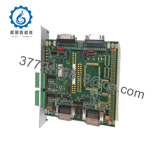
ACC-24E2
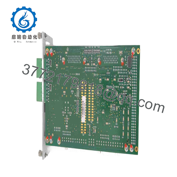
ACC-24E2
Frequently Asked Questions
What does the Delta Tau do?
The adds PMAC2-style motion-interface channels to a UMAC or MACRO Station system. It provides direct PWM servo outputs or pulse-and-direction outputs, encoder feedback inputs, limits, home inputs, user flags, amplifier-fault inputs, and position-compare capability. The base board supports two channels; an Option 1D piggyback card expands it to four channels.
Is the the same as the ACC-24E2A?
No. This is a critical distinction. The is the digital/direct-PWM servo interface version. The ACC-24E2A is the analog version and provides ±10 V torque, velocity, or sinusoidal-command outputs for analog servo amplifiers. They may belong to the same family and fit related UMAC systems, but they are not direct electrical substitutes.
Can I use the with a stepper drive?
Yes, but only when configured correctly. Each channel can use pulse-and-direction output instead of direct PWM output. The required channel jumpers must be installed, and the PMAC software output mode must also be set for the intended interface. The unit ships in direct PWM configuration, so do not expect a standard replacement board to drive a stepper amplifier without setup changes.
How many axes can one support?
The base provides two servo channels. Adding an Option 1D piggyback board exposes channels three and four, producing a four-axis assembly. A UMAC can support up to eight ACC-24E2x boards for up to 32 additional servo-interface channels, while standard MACRO Station CPUs have lower channel limits.
Can I hot-swap an motion card?
No. Shut down the rack and follow lockout/tagout procedures before removing or installing the card. This is not a hot-swappable field I/O module. Removing it under power can damage the UBUS/backplane interface, create motion faults, corrupt configuration assumptions, or expose the card to ESD. Save the PMAC configuration and photograph all switches and jumpers before removal.
What must I record before replacing the ?
Record the complete part number and board revision, S1 DIP-switch positions, E13 clock jumper position, E10/E11 amplifier-fault polarity jumpers, channel output-mode jumpers, encoder resistor-pack orientation, connector option, controller type, PMAC firmware version, servo-channel assignments, I-variable settings, amplifier model, and encoder wiring. Take clear photos before touching anything. Seriously—this avoids most replacement rework.
Why does an replacement show an encoder-loss or following-error alarm?
The new board may be fine. Typical causes are swapped A/B encoder channels, missing complementary encoder lines, incorrect single-ended versus differential resistor-pack configuration, missing encoder 5 V supply, unconnected cable shields, wrong PMAC encoder-decode settings, or an existing encoder cable defect disturbed during replacement. Verify signal quality at the connector before declaring the new board defective.
Is obsolete, and is there a direct replacement?
The belongs to the legacy Delta Tau UMAC/Turbo PMAC motion-control environment, and current availability should be treated as limited. Omron has announced discontinuation actions for several older PMAC/UMAC accessories because key components became unavailable, reinforcing the need to plan spares and modernization carefully. Do not assume a modern Power PMAC accessory is a drop-in replacement; new accessories may require a Power PMAC CPU, different I/O architecture, and application changes.
What condition should I buy for a production-critical spare?
For a critical spare, request New Original / New Surplus with photos of the original manufacturer label, packaging, and connector condition, or Refurbished (tested) with documented testing. A meaningful test should include +5 V power draw, UBUS recognition, all enabled axis channels, PWM or pulse/direction outputs, encoder-input counting, limit and home inputs, amplifier-fault logic, and sustained operation in a compatible UMAC rack. Ask for test photos or video and a written warranty before purchase.



