
 WhatsApp: +86 16626708626
 Email:
  Phone: +86 16626708626
Description
Key Technical Specifications
| Parameter | Value |
|---|---|
| Model | DLS-C30 |
| Manufacturer | DIMETIX |
| Product Type | Industrial laser distance sensor |
| Measurement Accuracy | ±3.0 mm |
| Repeatability | ±0.5 mm |
| Natural-Surface Measurement Range | 0.05–65 m |
| Reflective Target Range | 25–150 m |
| Maximum Measurement Rate | 6 Hz |
| Supply Voltage | 9–30 VDC |
| Current Consumption | Up to 0.6 A at 24 VDC |
| Laser Classification | Class 2, visible red laser |
| Analog Output | Programmable 0/4–20 mA |
| Serial Interfaces | RS-232 / RS-422 |
| Digital I/O | Digital input plus programmable digital outputs |
| Protection Rating | IP65 |
| Operating Temperature | -10 to +50 °C, single measurement |
| Continuous Measurement Temperature | -10 to +45 °C |
| Storage Temperature | -40 to +70 °C |
| Housing | Aluminum |
| Dimensions | 150 × 80 × 55 mm |
| Weight | Approximately 690 g |
| Mounting | 3 × M4 mounting points |
The DLS-C30 is specified for non-contact distance measurement on natural surfaces up to approximately 65 m and on suitable reflective targets up to 150 m. Its measurement accuracy is specified at ±3.0 mm, with a measurement rate up to 6 Hz.
The sensor provides RS-232 and RS-422 communication, a programmable 0/4–20 mA analog output, digital I/O, and external triggering capability. An external Profibus interface was also available as an accessory for DLS-series installations.
Product Introduction
The DIMETIX DLS-C30 is an industrial laser distance sensor for fixed, non-contact measurement of position, level, thickness, and object distance. It uses a visible Class 2 laser and provides measurement data through RS-232, RS-422, programmable analog output, and digital I/O, allowing integration with PLC, PC, and industrial measurement systems.
The C30 version provides ±3.0 mm measurement accuracy with a natural-surface range of 0.05–65 m. For suitable reflective targets, the specified range extends to 150 m. Its IP65 aluminum housing and 9–30 VDC supply make it suitable for fixed industrial installations such as conveyor positioning, material-level measurement, and large-object dimensional monitoring.
Installation & Configuration Guide
Stage 1 — Pre-Installation Preparation
- Confirm the exact DLS-C30 model and inspect the nameplate before installation.
- Verify the sensor’s supply requirement: 9–30 VDC for the standard C30 version.
- Isolate the DC supply before making electrical connections.
- Prepare an M4-compatible mounting tool, multimeter, appropriate communication cable, and PC configuration interface if required.
- Confirm the PLC or controller interface: RS-232, RS-422, analog 0/4–20 mA, or digital I/O.
- Check the target surface. Highly polished, reflective, transparent, or otherwise difficult surfaces can affect measurement stability.
- Establish a clear optical path between the sensor and target.
Stage 2 — Removing the Existing Sensor
- Record the existing sensor model, mounting position, cable routing, and configuration.
- Back up PLC scaling, alarm limits, communication parameters, and analog-input configuration.
- Remove power from the sensor.
- Disconnect the communication, analog, digital, and supply wiring.
- Remove the mounting hardware without changing the mechanical reference position.
- Inspect the mounting bracket and optical path for vibration, contamination, or mechanical damage.
Stage 3 — Installing the DLS-C30
- Mount the DLS-C30 using its three M4 mounting points.
- Align the optical axis with the intended measurement target.
- Maintain a stable mechanical mounting surface; vibration can introduce measurement variation.
- Connect the 9–30 VDC supply with correct polarity.
- Connect RS-232 or RS-422 if digital measurement data is required.
- Connect the programmable 0/4–20 mA output when using a PLC analog input.
- Configure digital outputs or external trigger functions according to the control-system requirements.
- If long-distance measurement uses a reflective target, verify that the target is positioned within the applicable reflective-target range.
- Confirm that the selected communication and output parameters match the PLC configuration.
Stage 4 — Power-On & Testing
- Check supply voltage and polarity before energizing.
- Power the sensor and verify the status LEDs.
- Confirm that the laser is operating normally without exposing personnel to the beam.
- Establish RS-232/RS-422 communication where applicable.
- Compare the sensor reading with a known reference distance.
- Check the PLC analog scaling if using the 0/4–20 mA output.
- Test digital outputs and external trigger functions if used.
- Run several measurements across the actual operating range.
- Check for unstable readings caused by vibration, target reflectivity, optical contamination, or excessive temperature.
- Save the verified configuration before returning the equipment to automatic operation.
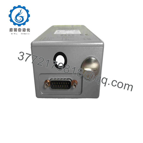
DLS-C30
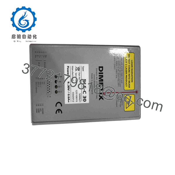
DLS-C30
Frequently Asked Questions
Q1. What does the DIMETIX measure?
It performs non-contact laser distance measurement. Typical industrial applications include conveyor position monitoring, fill-level measurement, roller or cylinder thickness measurement, and dimensional/position monitoring of large objects.
Q2. What is the maximum measurement distance?
The documented natural-surface range is approximately 0.05–65 m. With an appropriate reflective target, the specified range extends to approximately 25–150 m. Actual performance depends on target characteristics and installation conditions.
Q3. What accuracy does the provide?
The C30 variant is specified at ±3.0 mm accuracy. Repeatability is listed at approximately ±0.5 mm in available technical data. These figures should not be treated as guaranteed field accuracy for every target surface or environmental condition.
Q4. Can the connect directly to a PLC?
Yes. The sensor provides RS-232 and RS-422 interfaces and a programmable 0/4–20 mA analog output. A PLC can therefore receive measurement data through serial communication or an analog input, depending on the control architecture. An external Profibus interface was also available for the DLS series.
Q5. Is the suitable for outdoor or dusty industrial environments?
The enclosure is rated IP65, and the documented operating range for single measurements is -10 to +50 °C. Continuous measurement is specified to -10 to +45 °C. The sensor should still be protected from conditions that obstruct the optical path or produce unsuitable reflections.
Q6. Is the same as DLS-CH30?
No. The DLS-CH30 is the extended-temperature version. The standard is specified for -10 to +50 °C for single measurements, while the CH version is designed for operation down to -40 °C. Do not substitute the two variants without checking the environmental requirements and nameplate.
Q7. What should I verify before buying a replacement ?
Verify the complete model designation, physical nameplate, optical range, supply voltage, connector arrangement, communication interface, and existing PLC scaling. There is also conflicting secondary documentation regarding the part number, so the physical product label should take precedence over an unverified catalog number.



