
 WhatsApp: +86 16626708626
 Email:
  Phone: +86 16626708626
Description
Key Technical Specifications
- Manufacturer: Eaton / Cutler-Hammer
- Base Catalog Number: CE15KN3
- Product Type: Open three-pole magnetic contactor
- Product Family: Eaton Freedom / XT IEC contactor family
- Frame Size: K
- Number of Main Poles: Three
- Operation: Non-reversing
- Continuous Current Rating: 73 A for the documented CE15KN3AB variant
- Maximum Rated Voltage: 600 V AC on legacy CE15KN3 markings; verify the exact nameplate before installation
- Coil Voltage: Suffix-dependent; CE15KN3 alone does not identify coil voltage
- Documented CE15KN3AB Coil: 110–120 V AC, 50/60 Hz
- Overload Relay: Not included on the CE15KN3AB open-contactor configuration
- Approximate CE15KN3AB Dimensions: 4.22 in D × 2.56 in W × 4.27 in H
- Approximate CE15KN3AB Weight: 2.12 lb
- Approvals for CE15KN3AB: UL Listed, CSA Certified, IEC rated
- Mounting: Steel mounting plate / panel mounting
- Enclosure: No enclosure supplied with the documented configuration
- Warranty Reference: Eaton’s published warranty for is one year from installation or 18 months from shipment, whichever occurs first.
Important identification note: CE15KN3 is a base contactor designation. The letters following it identify the coil or variant. Do not order a replacement until you confirm the complete catalog number on the coil/nameplate, the control-circuit voltage, frequency, pole arrangement, auxiliary-contact requirement, overload arrangement, and actual motor-duty rating. Eaton identifies as a 73 A, three-pole, non-reversing Frame K contactor with a 110–120 V AC, 50/60 Hz coil.
Product Introduction
Eaton Cutler-Hammer CE15KN3 is a three-pole magnetic motor contactor from the Freedom/XT IEC contactor family. Plants use this frame size to switch three-phase motors, pumps, fans, compressors, conveyors, heaters, and similar AC loads through a separate control circuit.
The base number alone is not enough for a safe replacement. Coil voltage and suffix determine the exact unit. Confirm the full label before purchase, especially when replacing an older Series B1 or similar legacy contactor. The documented configuration is a 73 A, three-pole, non-reversing, open-frame contactor with a 110–120 V AC coil.
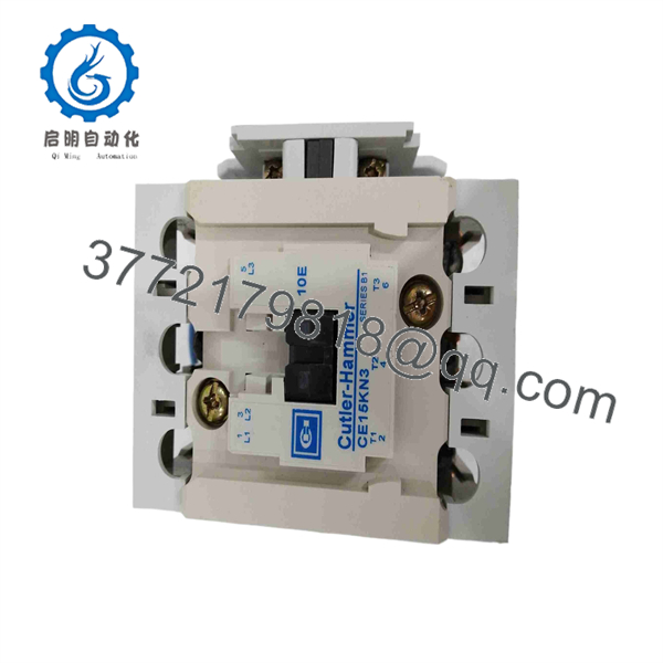
CE15KN3
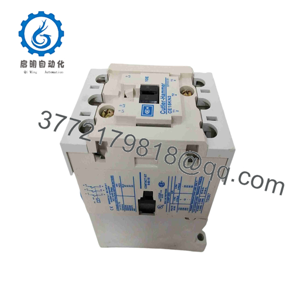
CE15KN3
Troubleshooting Quick Reference
| Symptom | Possible Cause | Relevance to This Part | Quick Check Method | Recommendation |
|---|---|---|---|---|
| Contactor does not pull in when commanded | Missing control voltage, blown fuse, open stop circuit, failed overload auxiliary contact, incorrect coil voltage | ✅ High | Measure voltage directly across coil terminals A1 and A2 while the start command is active; compare measured voltage and frequency with the coil nameplate | Fix the control circuit before replacing the contactor. If the correct coil voltage is present and the armature does not pull in, replace the contactor or coil assembly as applicable. |
| Contactor chatters or drops out | Low coil voltage, loose control wire, voltage dip during motor start, wrong coil frequency, failing control transformer | ✅ High | Trend or meter A1–A2 voltage during pickup and motor acceleration; inspect coil terminals and control-transformer output | Correct the voltage-drop problem first. Repeated chatter burns main contacts and can damage the coil. |
| Coil hums loudly but contactor pulls in | Armature contamination, worn shading ring on AC coil, loose laminations, low control voltage | ✅ High | Isolate power; inspect armature faces for dirt, corrosion, burrs, or damage; verify rated coil voltage at A1/A2 | Clean only as permitted by Eaton service guidance. Replace the contactor if the shading ring or magnetic assembly is damaged. |
| Motor does not start but contactor pulls in | Blown line fuse, open breaker pole, overload trip, failed motor, burned main contacts, open conductor | ✅ Medium | With proper lockout/tagout, measure line-to-line voltage on L1/L2/L3 and load-side T1/T2/T3; check voltage drop across each closed main pole | Check fuses, overload relay, motor circuit, and power wiring. Replace the contactor if closed contacts show abnormal voltage drop or heat damage. |
| One motor phase is missing after contactor closes | Burned or welded contact, loose line/load lug, failed fuse, damaged conductor | ✅ High | Measure all three phase-to-phase voltages at T1/T2/T3 with the contactor energized; compare each pole voltage drop under load | De-energize immediately if a phase is lost. Inspect terminals and contacts; replace damaged contactor components and correct the root cause. |
| Contactor runs hot or has a burnt odor | Loose lugs, undersized conductors, overloaded motor, high resistance contacts, excessive switching duty | ✅ High | Use an infrared camera under stable load; inspect for hot line/load terminals and compare phase current using a clamp meter | Re-torque connections to the published requirement, verify conductor sizing and motor current, and replace a contactor with heat-damaged contacts or insulation. |
| Contactor will not release after stop command | Welded main contacts, mechanically stuck armature, control voltage still present, incorrect holding circuit wiring | ✅ High | Remove the command signal, then measure A1–A2 for residual voltage; after lockout, inspect for welded contacts and mechanical binding | Correct holding-circuit wiring if voltage remains. Replace the contactor if contacts are welded or the armature is mechanically stuck. |
| New contactor does not fit or control circuit fails | Wrong suffix, wrong coil voltage, different auxiliary-contact arrangement, mounting-hole mismatch, incompatible overload attachment | ✅ High | Compare full catalog number, coil label, mounting dimensions, terminal locations, auxiliary contacts, and overload relay interface against the removed unit | Do not force the replacement into service. Confirm the complete Eaton/Cutler-Hammer suffix and application requirements. |
❗ Coil-voltage warning: CE15KN3 does not establish the coil voltage. The coil suffix does. A , for example, uses a 110–120 V AC, 50/60 Hz coil. Installing a 24 V coil into a 120 V control circuit can destroy it immediately; installing a 120 V coil on a 24 V circuit simply leaves you with a contactor that will not pull in.
❗ Contact inspection warning: Do not file, sand, or dress silver-alloy main contacts as a standard repair. Excessive abrasion changes the contact surface and contact pressure behavior. If contacts are welded, severely pitted, discolored from heat, or mechanically damaged, replace the appropriate contact kit only if the exact contactor version supports it; otherwise replace the complete contactor.
❗ Power-draw warning: A contactor coil can pull in reliably with no motor running yet chatter under actual plant conditions. Check A1–A2 voltage during the worst case: motor acceleration, starter operation, solenoid energization, or low battery/transformer conditions. A low control supply is often the cause, not the contactor.
❗ Terminal warning: Do not wire from memory. Older units may have different coil and auxiliary layouts than newer catalog variants. Verify line terminals, load terminals, coil terminals, auxiliary contacts, and overload interfaces against the exact nameplate and wiring diagram.
❗ Arc-flash warning: Perform voltage measurements only under an approved energized-work procedure with correctly rated PPE, meter leads, and arc-flash controls. For mechanical inspection or torque work, apply lockout/tagout, prove absence of voltage, and verify all sources are isolated.
Keep these checks in mind and you will save yourself 90% of typical rework time. If diagnosis remains uncertain, provide technical support with photos of the complete contactor label, coil label, control schematic, line/load terminals, measured A1–A2 voltage, motor current, and visible contact condition.
Frequently Asked Questions
What is the Eaton Cutler-Hammer ?
is a base model designation for a three-pole Eaton Cutler-Hammer magnetic contactor in the Freedom/XT IEC contactor family. It is used to switch three-phase motor and power loads through a lower-power control circuit. The exact electrical characteristics depend on the complete suffix. Eaton identifies as a 73 A, three-pole, non-reversing Frame K contactor.
What coil voltage does use?
You cannot determine coil voltage from alone. Check the complete part number and the coil label. For example, Eaton specifies with a 110–120 V AC, 50/60 Hz coil. Legacy units may use other coil options, so a purchase order based only on the base number is risky.
Take a photo of the coil marking and record both voltage and frequency. A 120 V AC coil, 24 V DC coil, and 230 V AC coil are not interchangeable.
Is rated for 73 A?
The documented Eaton variant carries a 73 A continuous-current rating. Some legacy market listings may describe other ratings or motor-duty values, and these can be affected by duty category, voltage, enclosure temperature, switching frequency, and the exact contactor variant. Use the nameplate and the OEM documentation for the precise unit you are installing.
Do not select a contactor based only on a motor’s nameplate horsepower. Verify full-load current, utilization category, supply voltage, starting duty, reversing duty if applicable, enclosure temperature, and short-circuit protective device coordination.
Is a reversing contactor?
Not by itself. Eaton lists as non-reversing. A reversing motor starter requires mechanically and electrically interlocked forward and reverse contactors, correct phase crossover wiring, and suitable overload protection. Do not attempt to create a reversing starter by improvising with a single non-reversing contactor.
Does include an overload relay?
The documented configuration does not include an overload relay. You must confirm whether your existing motor starter uses a separate overload relay, an attachable overload block, an electronic overload device, or motor protection in another part of the circuit. Eaton lists with “no overload relay.”
Never bypass motor overload protection just to get a failed starter operating. That shortcut can turn a contactor replacement into a burned motor or damaged feeder.
Can I hot-swap this contactor?
No. De-energize the line and control circuits, apply lockout/tagout, verify absence of voltage, and discharge any stored energy before replacing it. A contactor has exposed line and load terminals, and adjacent equipment may remain energized even if the motor is stopped.
To be honest, swapping a contactor live is not a time-saving move. It risks arc flash, phase-to-ground faults, damage to the new contactor, and serious injury. Use the plant electrical safety procedure and confirm all sources of control and power energy are isolated.
Why is a New Surplus cheaper than current factory stock?
New Surplus inventory typically comes from unused project stock, cancelled panel builds, distributor overstock, OEM spare holdings, or warehouse inventory from a discontinued or legacy product line. It can be genuine equipment, but condition and storage history matter.
For a New Original / New Surplus unit, require:
- High-resolution photos of the front label, coil label, terminals, and packaging
- Confirmation of the complete suffix, coil voltage, frequency, and pole count
- Inspection for corrosion, cracked plastic, heat discoloration, bent terminals, missing arc chambers, and prior installation marks
- Confirmation that auxiliary contacts, mounting hardware, and overload accessories are included only if specifically listed
- Written warranty terms and actual dispatch lead time
What quality testing should be completed before shipment?
A supplier should complete a documented inspection and test process:
- Inbound inspection and traceability: Verify source documents, catalog label, coil marking, date code where present, and original factory markings. Check for counterfeit labels, corrosion, rework marks, damaged terminal threads, worn armature surfaces, cracked housing, and UV yellowing.
- Visual mechanical inspection: Operate the armature manually with power isolated. Confirm free travel, complete return action, intact arc chambers, proper pole alignment, and secure terminal hardware. Check that auxiliary-contact blocks and overload accessories match the listing.
- Live functional testing: Energize the coil at its rated voltage and frequency using a protected test setup. Confirm pickup, hold-in, dropout, pole closure, and auxiliary-contact state. Test the actual coil rating shown on the label, not an assumed voltage.
- Electrical parameter testing: Verify coil continuity and insulation condition using the OEM-approved method. Check main-contact continuity when closed and verify no continuity when open. Perform insulation-resistance or dielectric testing only at ratings and procedures appropriate for the exact contactor.
- Load and thermal evaluation: When the supplier has suitable test equipment, run the contactor under representative controlled load and check for contact heating, coil overheating, abnormal noise, chatter, or inconsistent pickup.
- Final QC and packaging: Require QC inspector sign-off, terminal protection, moisture-resistant and impact-resistant packaging, heavy-duty corrugated boxing, and a dated QC-passed label. Test photos and a functional test record should be available upon request.



