
 WhatsApp: +86 16626708626
 Email:
  Phone: +86 16626708626
Description
Key Technical Specifications
| Parameter | Value |
|---|---|
| Model | DPM-MC2 |
| Manufacturer | Eaton Automation |
| Module Function | PROFIBUS Master |
| PROFIBUS Type | PROFIBUS, electrically isolated |
| Maximum Transmission Rate | 12 Mbit/s |
| Physical Interface | RS-485 |
| Connector | 9-pin female D-sub |
| PROFIBUS Standard | EN 50170 |
| Operating Temperature | 0 to +50 °C |
| Storage Temperature | -20 to +60 °C |
| Relative Humidity | 10–95%, non-condensing |
| EMC Standards | EN 61000-6-2, EN 61000-6-4 |
| PLC Equipment Standard | EN 61131-2 |
| Safety Standard | EN 60950 / UL 60950 |
| Product Standard | EN 50178 |
| XV-400 Catalog Number | COM-DPM-MC2 / 139853 |
| XV-400 Datasheet Temperature | 0 to +55 °C |
| XV-400 Module Dimensions | 110 × 20 × 140 mm |
| Safety Function Rating | Not suitable for safety functions |
The Eaton manual specifies DPM-MC2 as a PROFIBUS master for MICRO PANEL MC2 devices with the corresponding expansion slot. The XV-400 catalog identifies the related COM-DPM-MC2 module, catalog number 139853, as a PROFIBUS DP Master supporting 12 Mbaud.
Product Introduction
The Eaton DPM-MC2 is a dedicated PROFIBUS DP Master communication card for compatible MICRO PANEL MC2 platforms. It provides an isolated PROFIBUS interface through a 9-pin female D-sub connector and communicates over the RS-485 physical layer at rates up to 12 Mbit/s. Eaton specifies EN 50170-based PROFIBUS operation and provides status indication for communication and bus faults.
This module is primarily relevant to legacy Eaton/Moeller HMI-PLC installations that require PROFIBUS DP master communication with distributed I/O, drives, or other PROFIBUS devices. It is not a general-purpose Ethernet gateway or Modbus interface. The host panel must have the appropriate communication-card slot and configuration support.
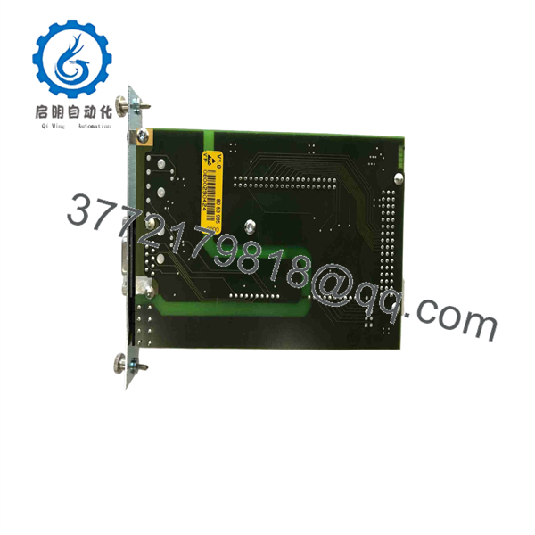
DPM-MC2
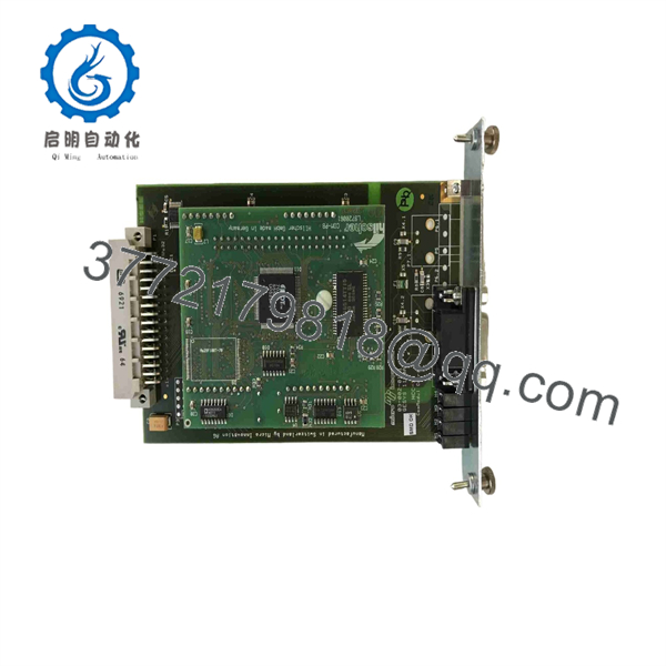
DPM-MC2
Installation & Configuration Guide
Stage 1 — Pre-Installation Preparation
- Verify the exact module marking: DPM-MC2. For XV-400 installations, also check whether the existing card is identified as COM- / 139853.
- Confirm that the target MICRO PANEL MC2/XV-400 hardware has the corresponding communication-module slot.
- Back up the HMI/PLC application, PROFIBUS configuration, node addresses, I/O mapping, and parameter files before removing the existing card.
- Shut down the machine using the plant’s approved isolation procedure and remove power from the host panel.
- Prepare ESD protection, a suitable screwdriver, the existing PROFIBUS connector, and configuration documentation.
- Do not remove or install the while the host device is energized. Eaton explicitly requires the card to be fitted and removed only in a de-energized state.
Stage 2 — Removing the Old Module
- Confirm that the panel is fully powered down and isolated.
- Remove the panel access hardware required to reach the communication-card slot.
- Record the existing card position and PROFIBUS connector orientation.
- Disconnect the 9-pin D-sub PROFIBUS connector without pulling on the cable.
- Release the module retaining mechanism and remove the card straight from the slot.
- Inspect the backplane connector and card guide for contamination, bent contacts, or mechanical damage.
Stage 3 — Installing the New Module
- Verify the replacement marking and connector configuration before insertion.
- Align the with the correct communication-card slot.
- Seat the module evenly without forcing the PCB or backplane connector.
- Reinstall the PROFIBUS connector and confirm the cable shield is properly retained.
- Check PROFIBUS termination. Eaton specifies termination at both ends of the bus segment and states that no more than two terminations should be activated on a segment.
- Restore the original configuration, including PROFIBUS master parameters, station addresses, GSD-based device configuration, and I/O mapping where applicable.
- Confirm that no configuration changes were unintentionally introduced during the replacement.
Stage 4 — Power-On & Testing
- Complete a final wiring and grounding inspection before energizing the panel.
- Power the MICRO PANEL back on and observe the status LEDs.
- READY indicates card readiness; RUN indicates PROFIBUS communication status; ERROR indicates a PROFIBUS error; STATUS indicates token/data activity.
- Check the master configuration and verify that configured PROFIBUS slaves reach the expected operational state.
- Confirm PLC/HMI I/O data exchange before returning the machine to automatic operation.
- Perform a controlled dry run and verify drive, remote-I/O, and alarm behavior.
- If RUN remains inactive or ERROR is illuminated, check the PROFIBUS configuration, node addresses, cable polarity, termination, shield connection, and slave diagnostics before replacing additional hardware.
Frequently Asked Questions (FAQ)
Q1: Is the Eaton a PROFIBUS master or slave?
It is a PROFIBUS DP Master. Eaton’s documentation explicitly identifies as a PROFIBUS master for compatible MICRO PANEL MC2 devices.
Q2: What is the maximum PROFIBUS communication speed?
The XV-400 version identified as COM- / catalog no. 139853 supports PROFIBUS DP Master communication up to 12 Mbit/s (12 Mbaud).
Q3: Can be installed while the HMI is powered?
No. Eaton’s manual states that the card must only be fitted or removed when the device is de-energized.
Q4: Is a direct replacement for an Ethernet or Modbus communication card?
No. is specifically a PROFIBUS interface. Eaton’s current datasheet identifies one RS-485 hardware interface and PROFIBUS support, while Modbus, PROFINET, EtherNet/IP, and TCP/IP are not listed as supported protocols for the COM- version.
Q5: What connector does the module use?
The uses a 9-pin female D-sub PROFIBUS connector. The documented signals include RxD/TxD-P, RxD/TxD-N, CNTR-P, DGND, VP, and cable shield.
Q6: Can be used for a safety function?
No. Eaton’s technical data does not assign a SIL or performance-level rating to the module and specifically identifies it as unsuitable for safety functions.
Q7: What should be verified before purchasing a replacement?
Verify the exact host panel, communication-card slot, module marking, catalog/part number, PROFIBUS configuration, and firmware/software environment. For XV-400 applications, compare the installed card against COM- / 139853 rather than relying only on the generic designation.



