 WhatsApp: +86 16626708626
 Email:
 Phone: +86 16626708626
Description
Key Technical Specifications
| Parameter | Value |
|---|---|
| Manufacturer | Eaton MTL |
| Model | MTL5053 |
| Product category | Intrinsically safe fieldbus isolator / power supply |
| Fieldbus data rate | 31.25 kbit/s |
| Fieldbus type | H1 fieldbus |
| Hazardous-area supply voltage | 18.4 V ± 2% |
| DC output impedance | 105 Ω ± 3% |
| Maximum output current | 80 mA |
| Fieldbus device location | Zone 0, IIC, T4–T6, when suitably certified |
| Bus termination | Internal terminator selectable by a switch on top of the module |
| Fieldbus power-supply classification | Fieldbus Foundation Type 133 |
| Replacement reference | MTL5553; confirm detailed equivalence |
| Dimensions and weight | Verify against the applicable OEM documentation |
| Operating temperature | Verify against the applicable product datasheet |
| Certification status | Varies by certificate and region; check the exact approval required |
Source: Eaton MTL5000 Series documentation and the MTL5053 product datasheet.
Engineering note: The MTL5053 is not a general-purpose analog signal isolator. Its function is to supply power and pass digital communications on an H1 fieldbus segment serving appropriately certified devices in hazardous areas. Do not substitute a generic 4–20 mA isolator based on terminal count or physical appearance.
Product Introduction
The Eaton MTL5053 is an intrinsically safe isolator and power supply designed to extend 31.25 kbit/s H1 fieldbus networks into hazardous areas. It supplies fieldbus devices through the signal conductors while maintaining the electrical isolation required by the intended installation. An internal termination resistor can be enabled when the bus layout requires termination at the module.
The MTL5053 is relevant to process-control installations that use H1 fieldbus instrumentation in hazardous locations. Before ordering a replacement, confirm the fieldbus segment design, device power requirements, termination arrangement, and applicable hazardous-area approvals. Eaton lists the MTL5553 as the nearest equivalent, but the replacement must be checked against the original system design.
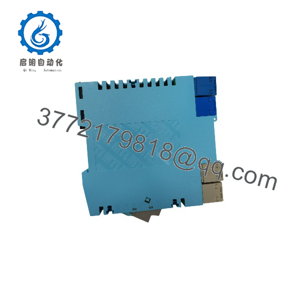
MTL5053
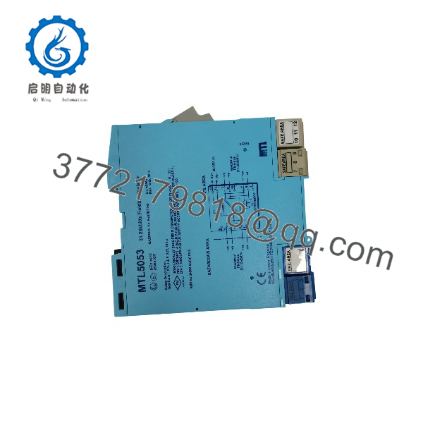
MTL5053
Installation & Configuration Guide
The following is a field-oriented replacement procedure. Actual wiring and commissioning time depend on access, documentation, hazardous-area permits, and the condition of the fieldbus segment. Do not assume a 30-minute replacement is achievable without first reviewing the installation.
Stage 1: Pre-Installation Preparation
Estimated time: 10–20 minutes
- Obtain authorization for the work. Notify operations and confirm the required process safe state, bypass arrangements, and permit requirements.
- Isolate the relevant power sources. Apply the site’s lockout/tagout procedure and verify the circuit is de-energized. Do not rely on a generic five-minute discharge interval; follow the equipment-specific instructions.
- Record the existing installation. Photograph the MTL5053 label, terminal connections, fieldbus wiring, DIN-rail position, and termination-switch setting.
- Check replacement suitability. Confirm the exact part number, hazardous-area certification, supply requirements, and intended fieldbus application.
- Prepare the tools. Have an appropriate multimeter, insulated screwdrivers, wire labels, an ESD wrist strap where applicable, and the approved wiring diagram available.
Stage 2: Remove the Existing Module
Estimated time: 5–10 minutes
- Verify that the affected fieldbus segment is in the approved maintenance state.
- Label each conductor before disconnecting it. Keep safe-area and hazardous-area wiring clearly identified.
- Disconnect the removable signal and power connectors according to the installation manual.
- Release the DIN-rail retaining clip and remove the module without damaging the rail or adjacent wiring.
- Inspect the terminals, conductors, connector plugs, and mounting rail for corrosion, loose connections, or heat damage.
- Retain the original unit until the replacement has passed commissioning.
The MTL5000 Series manual specifies DIN-rail mounting and removable signal and power connectors. It also calls for separation of safe-area and hazardous-area wiring where practicable.
Stage 3: Install the Replacement
Estimated time: 5–15 minutes
- Verify that the replacement is the correct model and that its certification is suitable for the installation.
- Mount the unit on the specified DIN rail and confirm that the retaining clip is engaged.
- Reconnect the conductors using the correct terminal assignments from the MTL5053 documentation. Do not rely on wire color or memory alone.
- Restore the original termination-switch setting only after checking the segment topology and confirming that the module is intended to provide termination at that location.
- Check conductor seating, terminal security, connector orientation, and separation of hazardous-area and safe-area circuits.
Pre-energization checklist
Stage 4: Power-On and Commissioning
Estimated time: 10–30 minutes, depending on the system
- Complete the site’s electrical safety checks before restoring power.
- Energize the fieldbus segment in accordance with the approved commissioning procedure.
- Measure the segment voltage at the appropriate test point and compare it with the network design and connected-device requirements.
- Confirm that the fieldbus host can communicate with the expected devices.
- Check for missing devices, communication errors, unexpected segment voltage, and termination-related faults.
- Verify that all affected control loops and alarms have returned to their expected states before handing the segment back to operations.
Troubleshooting guidance
- Devices fail to communicate: Check polarity, wiring continuity, segment voltage, termination, and the fieldbus host’s diagnostics.
- Multiple devices disappear simultaneously: Investigate the segment power supply, trunk wiring, and termination before replacing individual instruments.
- The replacement does not restore operation: Recheck the exact model and wiring against the OEM documentation. Do not assume that an MTL5553 replacement is electrically interchangeable without verification.
Intrinsic-safety installations require competent personnel and compliance with applicable site rules and certification requirements. Use the manufacturer’s instructions for the specific module and installation.
Frequently Asked Questions (FAQ)
Q1. Is the Eaton MTL5053 obsolete?
The MTL5053 is a legacy product, and Eaton’s documentation identifies several historical certifications as obsolete or terminated. Some listed approvals remain current in specific jurisdictions, so certification status must be checked against the destination market and installation requirements.
Q2. What is the direct replacement for the MTL5053?
Eaton’s discontinued-product cross-reference lists the MTL5553 as the nearest equivalent to the MTL5053. However, a cross-reference does not by itself establish suitability for every installation. Compare fieldbus power requirements, hazardous-area entity parameters, termination requirements, and certification before substituting the module.
Q3. Can the MTL5053 be hot-swapped while the fieldbus is running?
Do not assume that live replacement is permitted. Removing the module can interrupt fieldbus power or communications, and work on intrinsically safe circuits is subject to the installation’s protection concept and site procedures. Obtain approval from the responsible control-system engineer, follow the manufacturer’s instructions, and isolate the circuit when required.
Q4. Does the MTL5053 support 4–20 mA analog signals?
The MTL5053 is designed for 31.25 kbit/s H1 fieldbus, not as a conventional 4–20 mA analog isolator. If the application uses analog transmitters, select an interface specifically designed for that signal type. A fieldbus segment and a 4–20 mA loop have different electrical and communication requirements.
Q5. Is the MTL5053 available as new original stock?
Availability and condition depend on the supplier’s current inventory. Because this is a legacy model, request photographs of the actual unit, its identification label, and packaging before purchase. Ask the supplier to state the condition explicitly as new original, factory sealed, new surplus, or refurbished and tested. Do not treat packaging alone as proof of authenticity or functionality.
Q6. Why is the MTL5053 priced differently from newer alternatives?
Legacy inventory, remaining stock, condition, certification documentation, and supplier testing arrangements can all affect pricing. A lower purchase price does not necessarily mean lower total cost. For a critical process-control segment, also consider engineering validation, installation downtime, and the consequences of an incompatible replacement.
Q7. What should I verify before ordering an MTL5053?
Confirm the following with the supplier:
- Exact model number and readable product label.
- Physical condition and documented functional-test status.
- Fieldbus compatibility and the required output power.
- Applicable hazardous-area certificates and installation jurisdiction.
- Availability, dispatch lead time, warranty terms, and return policy.
- Whether the MTL5553 is a technically acceptable alternative for your specific installation.