
 WhatsApp: +86 16626708626
 Email:
  Phone: +86 16626708626
Description
Key Technical Specifications
- Manufacturer: Emerson
- Model Number: CE4002S1T2B5
- Common Associated Part Number: KJ3204X1-BA1
- Additional Associated Number: 12P3275X022
- Product Family: Emerson DeltaV Series 2 I/O
- Product Category: Standard I/O Termination Block
- Primary Function: Provides the field-wiring termination interface for the applicable DeltaV Series 2 I/O assembly
- System Role: Passive termination hardware; not a standalone DeltaV controller, power supply, or active I/O module
- Field Wiring: Signal-specific wiring depends on the installed I/O card, termination type, loop drawing, and system configuration
- Compatibility Requirement: Confirm the exact matching DeltaV I/O card, terminal-block position, field device type, and system cabinet documentation
- Replacement Requirement: Match all visible identifiers:
CE4002S1T2B5,KJ3204X1-BA1, and12P3275X022where present - Installation Practice: Isolate field circuits and use ESD-controlled handling before removing associated DeltaV I/O electronics
- Procurement Note: This part is often sold as an assembly reference with KJ3204X1-BA1; request photos of the actual label and included hardware before ordering
Available product references identify CE4002S1T2B5 as an Emerson Standard I/O Termination Block for DeltaV Series 2 I/O systems, and associate it with KJ3204X1-BA1 and 12P3275X022.
Product Introduction
Emerson CE4002S1T2B5 is a Standard I/O Termination Block used in DeltaV Series 2 I/O systems. It provides the physical field-wiring interface for the corresponding DeltaV I/O assembly, helping route field signals from transmitters, switches, valves, and other devices to the installed DeltaV electronics.
CE4002S1T2B5 is termination hardware, not an active controller or a universal I/O card. The right replacement depends on the complete assembly reference, paired I/O module, field signal type, and cabinet wiring layout. Confirm KJ3204X1-BA1 and 12P3275X022 against the installed hardware before purchase.
Troubleshooting Quick Reference
| Symptom | Possible Cause | Relevance to This Part | Quick Check Method | Recommendation |
|---|---|---|---|---|
| No DeltaV I/O card status indication | Missing system power, failed carrier or I/O card, controller/network issue | ❌ Low | Measure the applicable DeltaV I/O power supply at the cabinet distribution point; verify whether adjacent I/O cards show normal LEDs | Do not replace CE4002S1T2B5 first. Check power, carrier, active I/O card, and DeltaV diagnostics. |
| One field input reads open, zero, or out of range | Broken conductor, loose terminal, failed field transmitter, loop-power problem, incorrect channel configuration | ✅ Medium | Check field-loop continuity; measure signal at the termination point; compare the result with a handheld calibrator or transmitter local display | Correct field wiring, loop power, and configuration faults before replacing the termination block. |
| Several adjacent channels fail after maintenance | I/O card not fully seated, termination block installed incorrectly, connector issue, wiring landed on wrong terminals | ✅ High | Apply lockout/tagout as required; inspect card-to-terminal-block engagement; compare wire markers and terminal numbers to the approved loop drawings | Re-seat the correct hardware and verify every conductor. Replace the termination block only if connector damage or failed continuity is confirmed. |
| Analog signal is noisy or unstable | Shield grounding error, loose termination, induced noise, poor field grounding, damaged terminal contact | ✅ Medium | Inspect terminal screws and shield connections; compare the grounding method with the project drawing; trend signal value while checking cable movement under approved conditions | Fix shielding and grounding first. Replace only if terminal or internal connection damage is present. |
| Output device does not respond | Blown field fuse, output card fault, failed solenoid/positioner, open field cable, incorrect output configuration | ✅ Medium | Verify output command in DeltaV diagnostics; measure field supply and output voltage at the termination terminals; test the final element separately per site procedure | Separate the I/O card, field device, field power, and termination path before ordering a replacement block. |
| Replacement does not fit or terminal layout differs | Incorrect terminal block type, wrong DeltaV I/O card family, different keying, incorrect assembly reference | ✅ High | Photograph the removed unit front and rear, all labels, mating connector, and paired I/O card; compare with cabinet drawings | Stop the swap. Do not move wires based on a similar-looking terminal block. Confirm exact part numbers. |
| Visible corrosion, heat discoloration, cracked terminal body, or loose clamps | Water ingress, overcurrent, cabinet contamination, wiring fault, prior rework | ✅ High | De-energize, inspect for damaged insulation and terminals, then perform approved continuity checks between intended points | Replace the damaged termination block and correct the moisture, heat, or wiring root cause before energizing. |
❗ Configuration warning: does not normally hold the DeltaV control strategy, but the associated I/O card and DeltaV configuration determine signal behavior. Back up the relevant configuration, save diagnostics, and record channel assignments before removing hardware.
❗ Terminal-block warning: Take photographs before touching field wiring. Seriously. On a crowded DeltaV cabinet, it is easy to land an input, return, shield, or field supply on the wrong terminal. Similar terminal blocks may have different signal paths or keying arrangements.
❗ Wiring warning: Do not wire from memory. Check the approved loop drawing, cabinet wiring diagram, channel assignment, and terminal identification. Even when the terminal block looks identical, the paired I/O card may use a different pinout or field-power arrangement.
❗ Power warning: The termination block is usually not the primary source of current consumption, but field devices are. Before replacing output-related hardware, verify the field power supply under load and leave at least a 20% capacity margin on the associated supply.
❗ ESD warning: Wear a grounded wrist strap before handling DeltaV I/O cards and avoid placing electronics on cardboard, painted cabinet steel, or an unprotected workbench. I have seen a technician pull a working I/O card on a dry day, handle it without ESD protection, and turn a one-channel issue into a dead card. Use the strap.
Keep these checks in mind and you will save yourself 90% of typical rework time. If you are stuck, contact technical support with photos of the full label, paired I/O card label, cabinet terminal layout, field wiring, DeltaV diagnostics, and measured loop values.
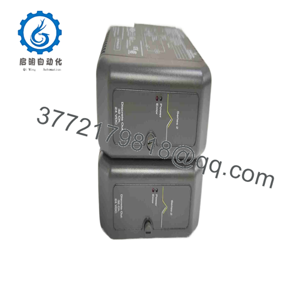
CE4002S1T2B5
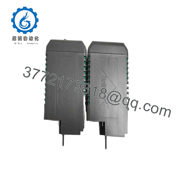
CE4002S1T2B5
Frequently Asked Questions
What is Emerson ?
Emerson is a Standard I/O Termination Block for an Emerson DeltaV Series 2 I/O installation. It provides the field-wiring interface associated with the matching DeltaV I/O hardware. Product listings associate this item with DeltaV reference KJ3204X1-BA1 and number 12P3275X022.
Is an active DeltaV I/O module?
No. It is a termination block, not the active I/O electronics. It does not replace a DeltaV controller, carrier, power supply, or I/O card. If the failed item has status LEDs, electronic diagnostics, firmware information, or channel-processing functions, the active I/O card may be the actual part you need.
Before ordering, identify both the termination block and the DeltaV I/O card installed with it.
Can I use as a replacement for any DeltaV terminal block?
No. Do not treat it as a universal replacement. DeltaV terminal hardware must match the I/O card family, signal type, terminal assignment, field-power method, cabinet arrangement, and mechanical keying. A mismatch can create an open circuit, miswire an output, damage a field device, or cause misleading DeltaV diagnostics.
The safe process is simple: compare the complete label, terminal numbering, associated identification, existing I/O card label, and approved cabinet drawings.
Can I hot-swap this termination block?
Do not hot-swap it unless Emerson’s exact documentation and your plant maintenance procedure explicitly permit it. This component carries field conductors, and removal can interrupt live signals, create nuisance alarms, command an output to a fail state, or affect safety-related operation.
To be honest, a live terminal-block change is rarely worth the risk. Isolate the affected loops, apply approved bypasses where necessary, follow lockout/tagout requirements, prove the circuit safe, and label every conductor before removal.
Will replacing erase my DeltaV configuration?
Normally, no. The termination block does not typically store the control strategy, I/O database, graphics, or controller configuration. However, replacing it may expose existing wiring, scaling, channel-type, or I/O-card configuration errors.
Before the swap:
- Save DeltaV diagnostics and channel status information
- Record all alarm and bad-status conditions
- Photograph terminal numbers, wire labels, shield connections, and jumper positions
- Identify the paired I/O module and its exact part number
- Verify the approved loop diagram against actual field wiring
Why is a New Surplus cheaper than factory supply?
New Surplus equipment normally comes from unused project spares, cancelled DeltaV expansions, distributor overstock, site warehouse inventory, or a decommissioned but never-installed stockholding. The lower price often reflects secondary-market sourcing and legacy inventory status, not automatically a functional problem.
Still, do not accept vague descriptions. Request:
- Actual photos of the complete label and terminals
- Confirmation of New Original, New Surplus, or Refurbished condition
- Confirmation of included connectors, terminal accessories, or mounting parts
- Evidence that the unit has no corrosion, heat marks, rework, broken clamps, or damaged contacts
- Warranty duration, return conditions, actual stock quantity, and dispatch lead time
What inspection and testing should a supplier complete before shipping?
For a sold as New Original / New Surplus, request a documented inspection sequence:
- Inbound inspection and traceability: Verify the full part number, associated labels, source documents, OEM markings, and packing information. Inspect for serial-number alteration, counterfeit labels, cracked housings, UV yellowing, corrosion, scratches, terminal damage, or rework marks.
- Mechanical and terminal inspection: Examine field terminals, connector contacts, keying features, mounting points, and retention hardware. Ensure clamps are intact and that there are no bent contacts, stripped screws, or signs of prior wiring.
- Mated fit and functional evaluation: Where a compatible DeltaV Series 2 test assembly is available, install the correct paired I/O hardware and confirm physical fit, connector engagement, and representative signal-path continuity. Remember that a termination block cannot be validated as a complete active I/O system without the matching I/O card.
- Electrical checks: Use a calibrated Fluke 115 or equivalent to verify intended continuity paths and absence of unintended shorts. Apply insulation-resistance or hipot testing only if the OEM procedure specifically approves it for this termination assembly; indiscriminate high-voltage testing can damage connected electronics.
- Configuration documentation: Photograph labels, terminal layout, keying, and included components. If the matched I/O card is included, document its firmware and configuration separately.
- Final QC and packing: Require QC sign-off, ESD-safe handling for electronic assemblies, anti-static bagging where appropriate, bubble wrap, heavy-duty corrugated packaging, and a dated QC-passed label. Test photos and inspection records should be available upon request.



