
 WhatsApp: +86 16626708626
 Email:
  Phone: +86 16626708626
Description
Key Technical Specifications
| Parameter | Value |
|---|---|
| Manufacturer | Emerson |
| Current Brand Association | Vertiv |
| Model | HD22010-3 |
| Product Type | High-frequency switching rectifier / charging module |
| Rated DC Output Voltage | 220 VDC |
| Rated DC Output Current | 10 A |
| Maximum Output Current | 11 A |
| AC Input | 3-phase, 3-wire |
| Input Voltage | 323–475 VAC |
| Input Frequency | 45–65 Hz |
| Adjustable Output Voltage | 176–320 VDC |
| Efficiency | ≥92% |
| Power Factor | ≥0.94 |
| Voltage Regulation | ≤±0.5% |
| Current Regulation | ≤±0.5% |
| Ripple Factor | ≤0.1% |
| Current-Sharing Imbalance | ≤±5% |
| Communication | RS485 |
| Cooling | Natural cooling + forced-air cooling |
| Operating Temperature | −10 to +40 °C |
| Protection | Overvoltage, undervoltage, overcurrent, short circuit, overtemperature, phase-loss power limiting |
| Approx. Output Power | 2.2 kW |
| Approx. Dimensions | 413 × 110 × 257 mm |
| Approx. Weight | <8 kg |
The published specifications above are supported by current industrial listings, while an older technical discussion provides additional system-level information and identifies ordering code 02130517 for HD22010-3.
Product Introduction
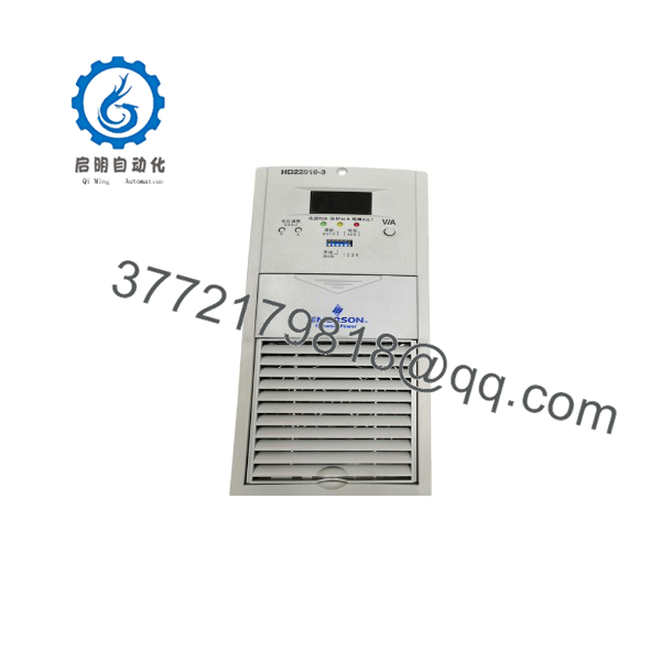
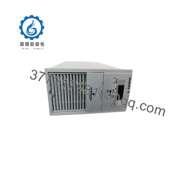
The Emerson HD22010-3 is a high-frequency switching rectifier and battery-charging module designed for 220 VDC industrial and utility DC power systems. It accepts three-phase AC input and provides a regulated DC output for battery charging and DC loads in substation and plant power systems.
The module uses a three-phase passive PFC front end followed by a high-frequency DC/DC conversion stage. It supports RS485 monitoring, current sharing between parallel modules, and natural/forced cooling. The design also incorporates input and output protection functions for DC power-system operation.
Installation & Configuration Guide
Stage 1: Pre-Installation Preparation — 10–15 minutes
⚠️ Safety First: HD22010-3 operates from hazardous three-phase AC and produces a high-voltage DC output. Isolate the AC input and DC output circuits, apply lockout/tagout, and verify the absence of hazardous voltage before removal.
Tools Required:
- CAT-rated multimeter
- Insulated screwdrivers
- ESD wrist strap
- Wire labels
- Smartphone/camera
- DC-system wiring drawings
- Module communication documentation
Data Backup:
- Record the complete HD22010-3 model number.
- Photograph the module nameplate.
- Record the system’s DC voltage setting.
- Photograph AC input and DC output connections.
- Record RS485 wiring and address settings if used.
- Photograph the module position in the DC panel.
- Record the monitoring system configuration.
- Keep the original module until the replacement is fully commissioned.
Stage 2: Removing the Old Module — 5–10 minutes
- Isolate the AC input.
- Isolate the DC-side connection according to the DC panel manufacturer’s procedure.
- Verify voltage at the relevant terminals.
- Label all AC, DC, communication, and auxiliary connections.
- Disconnect the wiring carefully.
- Release the module’s mechanical retaining mechanism.
- Remove the module using its designated handles.
- Inspect the connector and rack/backplane contacts.
- Check for signs of overheating or damaged terminals.
⚠️ Do not assume that removing the AC supply makes the DC terminals safe. The battery bank and DC bus can remain energized independently of the rectifier module.
Stage 3: Installing the New Module — 5–10 minutes
- Verify the replacement is HD22010-3.
- Compare the physical dimensions and connector arrangement with the original.
- Inspect the module for damaged connectors, fan obstruction, or mechanical damage.
- Insert the module into the correct slot.
- Ensure the power connectors are fully seated.
- Reconnect AC input wiring.
- Reconnect DC output wiring.
- Reconnect RS485 communication if used.
- Confirm polarity on the DC output.
- Verify that the cooling path is unobstructed.
Self-Checklist:
- model confirmed
- AC input wiring correct
- DC polarity verified
- RS485 wiring verified
- Module fully seated
- Cooling path clear
- Mounting hardware secured
- Monitoring system connection checked
Stage 4: Power-On & Testing — 10–20 minutes
- Confirm the DC system is in a safe operating state.
- Verify the three-phase AC input voltage.
- Energize the rectifier module according to the system procedure.
- Observe the module indicators and display.
- Verify that the module starts without an alarm.
- Check the DC output voltage.
- Verify output current.
- Check RS485 communication with the monitoring unit.
- Verify current sharing if multiple rectifier modules are installed.
- Test charging operation under controlled conditions.
- Confirm that no overvoltage, phase-loss, overtemperature, or communication alarm appears.
- Return the DC system to normal service only after the module passes the system test.
⚠️ Check the system’s configured float/boost charging voltage before commissioning. A 220 VDC nominal system can use different charging voltages depending on battery type and the DC system design.
Technical Architecture
The uses a two-stage power-conversion architecture:
Three-phase AC → EMI filtering / passive PFC → DC link → high-frequency DC/DC conversion → rectification/filtering → regulated DC output
The published technical description states that the front-end three-phase passive PFC performs rectification, filtering, and input-current correction, while the DC/DC stage uses PWM control and high-frequency transformation to generate the required DC output.
For systems with multiple charging modules, the can operate in parallel with current-sharing control. This is particularly relevant when one module is being replaced in an operating DC-panel system.
HD22010-3
HD22010-3
Frequently Asked Questions (FAQ)
What is the Emerson ?
The is a high-frequency switching rectifier and charging module for utility and industrial DC power systems. It converts three-phase AC power into regulated 220 VDC output and is used in DC panels for applications such as substations and power plants.
What is the rated output of ?
The nominal output is 220 VDC at 10 A, corresponding to approximately 2.2 kW. Current technical listings specify a maximum output current of approximately 11 A.
What input voltage does require?
The commonly published specification is 323–475 VAC, three-phase, three-wire, 45–65 Hz. Verify the actual system input before installation.
Can be hot-swapped?
The is described in available product documentation as supporting live insertion/removal for online maintenance. However, whether hot replacement is permissible in a particular installation depends on the DC panel rack, system wiring, battery condition, and site operating procedure. Do not perform a live replacement unless the complete system documentation explicitly permits it.
Does support ?
Yes. Current technical listings identify an communication interface for monitoring and system integration.
How does the cooling system work?
The module uses natural cooling at lighter loads and temperature-controlled forced-air cooling at higher thermal loads. Keep the air inlet and exhaust path clear during installation.
What protections are built into ?
The documented protection functions include input overvoltage/undervoltage protection, output overvoltage protection, overcurrent protection, short-circuit protection, overtemperature protection, and phase-loss power limiting.
Is still a current-production Emerson module?
The model is a legacy Emerson power-system product and is now commonly found through specialist industrial inventory. Current listings associate the Emerson product family with Vertiv, so buyers should verify the exact manufacturer labeling, material/ordering number, and physical condition before purchasing.



