
 WhatsApp: +86 16626708626
 Email:
  Phone: +86 16626708626
Description
Key Technical Specifications
| Parameter | Specification |
|---|---|
| Part Number | 1C31204G01 |
| Manufacturer | Emerson / Westinghouse |
| System | Emerson Ovation DCS |
| Module Type | Remote Node Controller PMOD |
| PMOD Function | Remote Node Personality Module |
| Compatible EMOD | 1C31203G01 |
| Optical Wavelength | 850 nm |
| Media | Fiber optic |
| Remote Node Base | 1C31205 |
| Diagnostic Interface | RS-232 |
| Optical Connections | RX / TX |
| Supply Monitoring | Redundant +24 V supply monitoring |
| Typical Remote Link | Up to 2 km configuration |
| Module Classification | Personality Module (P) |
| CE Mark Availability | Documented as available |
Emerson’s Ovation documentation identifies 1C31204G01 specifically as the Remote Node Personality Module for 850 nm optics. It houses the Remote Node Personality Board, provides the fiber-optic transmit/receive interface, and monitors the redundant +24 V supplies for the remote-node electronics. The corresponding 1300 nm version is 1C31204G03.
The documented Remote Node Controller architecture pairs the 1C31203 electronics module with 1C31204G01/G03 personality modules. The 1C31204G01 is therefore not a standalone Remote Node Controller; it is the optical PMOD portion of that assembly.
Product Introduction
The Emerson Ovation 1C31204G01 is a Remote Node Controller Personality Module designed for 850 nm fiber-optic communication in an Ovation remote I/O node. It provides the physical optical interface between the remote-node electronics and the fiber link back to the Ovation controller architecture.
The module also contains circuitry for monitoring redundant +24 V supplies and reporting supply faults to the associated electronics module. For procurement, the critical checks are the 1C31204G01 part number, 850 nm optical configuration, 1C31203G01 EMOD pairing, and existing 1C31205 remote-node base.
Installation & Configuration Guide
Stage 1 — Pre-Installation Preparation — 5–10 min
- Apply LOTO and place the Ovation remote I/O system in the approved maintenance state.
- Confirm the replacement nameplate reads 1C31204G01.
- Verify that the installed Remote Node Controller electronics module is the compatible 1C31203G01 configuration.
- Confirm the optical network uses 850 nm equipment.
- Photograph the existing module, fiber connectors, terminal/base arrangement, and status indicators.
- Label the RX and TX fiber connections before removal.
- Prepare:
- ESD wrist strap
- PH1 screwdriver
- Digital multimeter
- Fiber inspection/cleaning equipment
- Labels
- Smartphone/camera
- Back up relevant Ovation configuration and record the remote-node address and communication status.
⚠️ Do not substitute the 1300 nm 1C31204G03 for the 850 nm 1C31204G01 without verifying the complete optical architecture. Emerson documents these as different Remote Node Personality Module configurations.
Stage 2 — Removing the Existing Module — ~5 min
- Verify the remote node is safely isolated.
- Record existing status LEDs and communication alarms.
- Identify and label the fiber RX/TX connections.
- Carefully disconnect the optical connectors.
- Release the module retention mechanism.
- Remove the PMOD without twisting or forcing the connector.
- Inspect the module base and mating connector.
- Inspect the fiber connectors for contamination or damaged ferrules.
- Keep the removed module until the replacement passes communication testing.
⚠️ Fiber contamination can create intermittent communication faults that look like a controller or PMOD failure. Clean and inspect optical connectors before reconnecting them.
Stage 3 — Installing the 1C31204G01 — 5–10 min
- Verify the exact replacement part number: 1C31204G01.
- Verify the installed EMOD and base configuration.
- Confirm the optical network is 850 nm.
- Inspect the PMOD connector and housing.
- Use ESD protection when handling the module.
- Align the PMOD with its mating interface.
- Seat the module evenly.
- Reconnect the fiber cables according to the recorded RX/TX identification.
- Inspect the fiber connections again after installation.
- Confirm the remote-node base and module retention mechanism are secure.
Installation Self-Check
- 1C31204G01 verified
- 1C31203G01 EMOD verified
- 1C31205 base verified
- 850 nm optical architecture verified
- RX/TX fiber identification confirmed
- Optical connectors cleaned/inspected
- PMOD fully seated
- ESD precautions maintained
Stage 4 — Power-On & Testing — 10–15 min
- Perform a final visual inspection.
- Verify the remote-node supply conditions before energizing.
- Restore power according to the approved Ovation procedure.
- Check the remote-node status indicators.
- Confirm the controller recognizes the remote node.
- Verify the optical communication path.
- Confirm that redundant +24 V supply monitoring reports the expected status.
- Verify remote I/O communication with representative points.
- Check controller diagnostics for communication or node errors.
- Do not return the remote I/O node to automatic process operation until communication remains stable under the normal operating load.
Supplier Acceptance / QC Checklist
For a shutdown-critical spare, the supplier acceptance record should include:
- Exact 1C31204G01 part-number verification
- Serial/traceability information where available
- PCB and connector visual inspection
- ESD-controlled handling
- 850 nm optical-interface verification
- Power-up test
- RX/TX communication test where an appropriate Ovation test setup is available
- Redundant supply-monitoring verification
- Connector/fiber inspection
- Final QC inspection and ESD-safe packaging
A useful supplier test report should state what optical test was performed, not simply say “tested.”
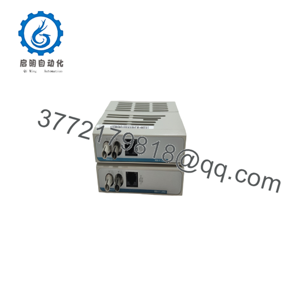
1C31204G01
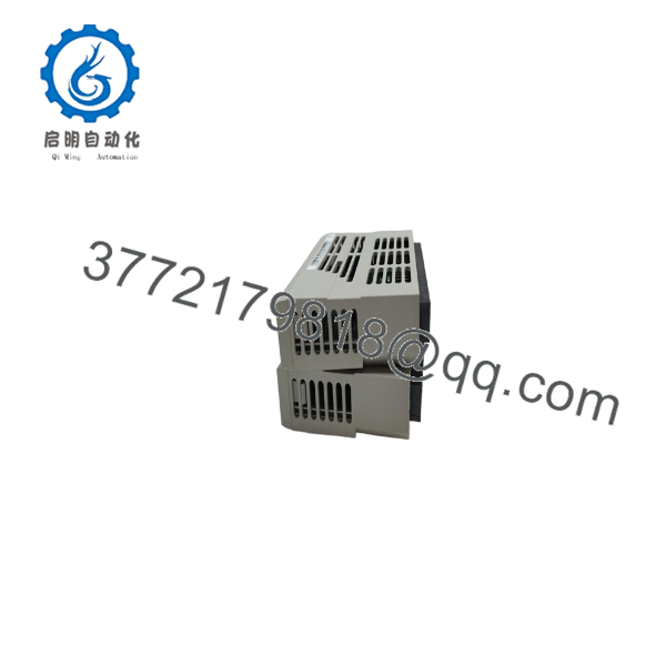
1C31204G01
Technical Pitfall & Survival Guide
1. G01 vs. G03 Optical Wavelength
The most important distinction is the optical wavelength. 1C31204G01 is the 850 nm version; 1C31204G03 is the 1300 nm version. Do not select the replacement solely by mechanical fit.
2. PMOD vs. EMOD Confusion
The 1C31204G01 is a PMOD, while 1C31203 is the Remote Node Controller electronics module. Current Emerson spare-parts documentation explicitly lists 1C31203G01 as the EMOD and 1C31204G01 as the 850 nm PMOD.
3. RX/TX Fiber Reversal
Fiber links are directional. Label the receive and transmit paths before removal and verify them after installation. A powered module with reversed fiber connections can appear healthy locally while the remote node remains offline.
4. Redundant +24 V Monitoring
The PMOD contains monitoring circuitry for the redundant +24 V supplies and reports supply failures to the electronics module. If the node reports a supply alarm after replacement, check the redundant supply path rather than immediately replacing the PMOD again.
5. Link-Distance Claims
The 1C31204G01 is associated with the 850 nm remote-node configuration, commonly documented as a 2 km optical arrangement. Treat 2 km as a system-configuration specification rather than a guarantee for every fiber installation; connector losses, fiber type, optical budget, and installed equipment must still be checked.
6. Legacy Procurement
Current aftermarket sources identify the 1C31204G01 as discontinued, while surplus and used units remain available. Emerson’s own spare-parts documentation continues to identify the part number, so an existing Ovation installation may still require it as a maintenance spare.
Frequently Asked Questions (FAQ)
1. What is Emerson 1C31204G01?
1C31204G01 is the Remote Node Controller Personality Module for 850 nm fiber optics in an Emerson Ovation system. It provides the fiber-optic media interface and redundant power-supply monitoring functions.
2. What is the difference between 1C31203G01 and 1C31204G01?
1C31203G01 is the electronics module (EMOD), while 1C31204G01 is the personality module (PMOD). They form the Remote Node Controller assembly.
3. Is 1C31204G01 an 850 nm or 1300 nm module?
850 nm. Emerson documentation identifies 1C31204G03 as the corresponding 1300 nm PMOD.
4. What base is used with the Remote Node Controller?
The Remote Node Controller uses the 1C31205 Remote Node Controller Base. The base can accommodate Remote Node modules and provides the interface to additional I/O branches.
5. Does 1C31204G01 have a diagnostic port?
The complete 1C31204G01 Remote I/O Node is documented by current aftermarket listings with an RS-232 diagnostic port, in addition to its RX/TX optical connections. Verify the exact hardware revision if the diagnostic interface is required for commissioning.
6. Is 1C31204G01 obsolete?
It is a legacy/discontinued component. Current aftermarket listings identify it as discontinued by the manufacturer, while used and surplus inventory remains available.
7. What should I verify before purchasing?
Verify 1C31204G01, the associated 1C31203G01 EMOD, 1C31205 base, 850 nm optical architecture, RX/TX fiber configuration, and actual product condition. For a critical spare, request photographs of the actual nameplate and a functional-test report before shipment.



