
 WhatsApp: +86 16626708626
 Email:
  Phone: +86 16626708626
Description
Key Technical Specifications
| Parameter | Value |
| Interface Array | 30 x 10/100/1000BASE-T RJ-45 fixed ports |
| Architecture | Distributed Forwarding Engine (DFE) with localized lookup and switching |
| ASIC Technology | Enterasys proprietary nTERA ASICs |
| Chassis Compatibility | Matrix E7 and Matrix N-Series multi-slot switch enclosures |
| Layer Capacity | High-performance wire-speed Layer 2 switching, Layer 3 routing, and L4 policy enforcement |
| Expansion Slot | Supports optional Network Expansion Modules (NEM) for uplink scaling |
| Quality of Service | Advanced packet classification, priority queuing, and rate-limiting profiles |
| Physical Form Factor | Hot-swappable proprietary chassis blade |
| Shipping Weight | Approximately 14.00 lbs (6.35 kg) |
| Dimensions | 18.27 x 11.61 x 2.40 inches (46.4 x 29.5 x 6.1 cm) |
Product Introduction & Supply Chain Strategy
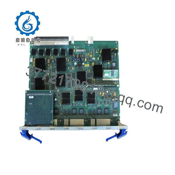
The Enterasys 7G4202-30 is a Platinum-tier Distributed Forwarding Engine (DFE) designed as a core switching and routing blade for the chassis-based Matrix E7 and Matrix N-Series platforms. Powered by specialized Enterasys nTERA ASICs, this high-density 30-port Gigabit module offloads system-wide congestion by handling packet lookups, localized switching, and Layer 2/3/4 policy containment directly on the board. This decentralized processing methodology prevents the communication backplane from becoming a single bottleneck, making the card ideal for network edge distribution, collapsed backbones, and server aggregation arrays within large scale automation or enterprise setups.
Because this platform is highly specialized and long discontinued by the OEM, sourcing the 7G4202-30 as a New Surplus asset represents an essential protective procurement policy. Substituting un-deployed cards with low-cost refurbished or pulled alternatives exposes the backplane to volatile risks, such as microscopic traces of pin corrosion, damaged capacitor arrays, and localized interface fatigue that bypass quick multi-meter testing. Securing original, un-deployed inventory protects your facility’s Total Cost of Ownership by minimizing sudden packet-loss disruptions and circumventing severe emergency replacement delays that can cripple multi-slot industrial networks for days.

- 7G4202-30
Installation & Configuration Guide
Stage 1: Pre-Installation (Prep & Safety)
- Verify the targeted chassis layout (Matrix E7 or N-Series) and verify that the current power budgeting modules have ample head-room to support the added DFE.
- Put on a standard grounded anti-static wrist strap, connecting the alligator lead to the dedicated ESD grounding point on the rack frame.
- Access the active chassis management console and run
show configandshow systemto log current firmware versions, slot assignments, and module pairings. - Inspect the faceplate ejector levers on the New Surplus 7G4202-30 module to ensure they engage and unlatch smoothly.
Stage 2: Removal
- Identify the slot location of the faulty or legacy module requiring replacement.
- If removing an active card, gently disengage all 30 attached RJ-45 Ethernet network cables, taking care to tag each line corresponding to physical port numbering.
- Loosen the captive retaining fasteners located on the upper and lower edges of the module faceplate.
- Press the top and bottom ejector clips outward simultaneously to seat the internal backplane pins away from the chassis midplane, then slowly slide the heavy module straight out along the guide tracks.
Stage 3: Installation (Clone & Seat)
- Extract the New Surplus 7G4202-30 card from its specialized anti-static packaging inside your static-controlled workspace. Do not touch the gold contact tabs or delicate surface-mounted capacitors.
- Align the horizontal circuit board edges with the open chassis channel slots.
- Push the module gently backward into the chassis slot until the card faceplate meets the outer structure frame.
- Push both configuration ejector levers inward toward the faceplate to force the high-density alignment pins cleanly into the chassis midplane receptacle. Tighten the captive faceplate retention screws.
Stage 4: Power-On & Testing
- Re-insert the 30 RJ-45 patch lines into their original, dedicated port positions on the new interface array.
- Monitor the integrated front-panel LED indicators; the system self-test light must move through initialization cycles and settle into an active operational state without triggering a localized diagnostic fault lamp.
- Connect your terminal computer to the chassis core management port and verify slot initialization via CLI.
- Run the
show slotcommand to check that the newly integrated 7G4202-30 module has achieved an operational status handshake and automatically synced its localized switching tables.
Firmware/Software Versions & Upgrade Notes
The Distributed Forwarding Engine series runs custom firmware images tied strictly to the baseline Matrix OS hierarchy. To guarantee complete software compatibility across multi-slot chassis arrays, matching the firmware build running on the new blade to the rest of your system is mandatory.
⚠️ CRITICAL FIRMWARE INTEGRATION WARNING: When inserting a New Surplus 7G4202-30 DFE module into an active, running chassis stack, ensure that its pre-loaded image matches the major revision of your existing master node. Inserting a replacement blade pre-loaded with legacy firmware (such as pre-5.x or pre-6.x) into a chassis running modern image partitions (like 7.11.x) can result in boot-loop synchronization failures, or can cause the new module to hang during its initial communication handshake. Always document configuration parameters and review specific OEM release matrices before executing code adjustments via TFTP.
Frequently Asked Questions (FAQ)
What makes this New Surplus module superior to a refurbished option found on secondary markets?
A New Surplus 7G4202-30 module ensures that the unit contains pristine internal traces, un-degraded nTERA ASIC modules, and completely clean connector interfaces. Refurbished equivalents are often salvaged from decommissioned enterprise centers where they have accumulated thousands of operational thermal cycles, which drastically reduces their future service life and introduces unpredictable communication drops into your chassis backplane.
Does this module feature integrated fiber connections, or is it strictly copper?
The core 7G4202-30 configuration features 30 fixed 10/100/1000BASE-T RJ-45 copper interfaces. However, if your system topology demands high-speed fiber uplinks, the logic board contains an internal expansion bay that accommodates optional Network Expansion Modules (NEM) to supply dedicated high-speed fiber output directly from the card.
Can I hot-swap this DFE module while the rest of the Matrix chassis remains online?
The physical mechanical design of the Matrix E7 and N-Series chassis does permit the hot-swapping of peripheral DFE modules. However, if the target card is acting as the primary master router or configuration coordinator for the entire node, pulling it live without an established redundant pair will trigger immediate network failovers. Always run diagnostic checks on your chassis redundancy profile before extracting any active logic engine.
How does the distributed forwarding architecture of this card benefit my facility?
Because this unit functions as a Distributed Forwarding Engine, it contains autonomous processing resources and localized forwarding tables directly on the blade. When data traffic enters any of the 30 RJ-45 ports, the onboard nTERA ASICs execute switching lookups locally rather than routing all queries through a centralized master processor, drastically cutting latency and preventing data bottlenecks across the midplane.
What should I do if the module displays a solid amber or red fault light upon insertion?
A persistent error light typically indicates either a backplane pin seating misalignment or a serious firmware version mismatch against the chassis controller. Unfasten the retaining screws, open the ejector clips to break contact, slide the card halfway out, and verify that no physical obstructions are blocking the path before reseating the module firmly into the midplane slots.
What warranty terms back this legacy Enterasys hardware?
We bundle a comprehensive 1 year replacement warranty with this New Surplus product. In the unlikely event that any of the 30 copper interfaces or localized ASICs fail to initiate properly under normal operational configurations, our team will provide a replacement unit to ensure your legacy chassis network maintains maximum runtime integrity.



