
 WhatsApp: +86 16626708626
 Email:
  Phone: +86 16626708626
Description
Key Technical Specifications
| Parameter | Value |
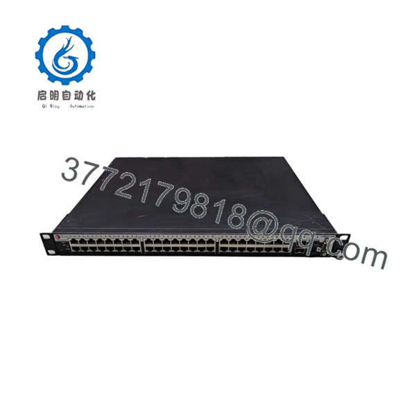
| Port Density | 48 x 10/100/1000BASE-T RJ-45 fixed ports with full PoE support |
| Uplink Interfaces | 4 x SFP Gigabit Ethernet combo ports (shared with last 4 RJ-45 ports) |
| Stacking Architecture | Integrated hardware stacking ports (Up to 8 units per stack via dedicated stacking cables) |
| PoE Standards | IEEE 802.3af Power over Ethernet compliant |
| Forwarding Capacity | Wire-speed L2 switching and L3 routing architecture |
| Policy Enforcement | Layer 2/3/4 classification, user-based policy provisioning, and hardware-enforced ACLs |
| Management Framework | NetSight suite integration, Command Line Interface (CLI), and embedded Web Server |
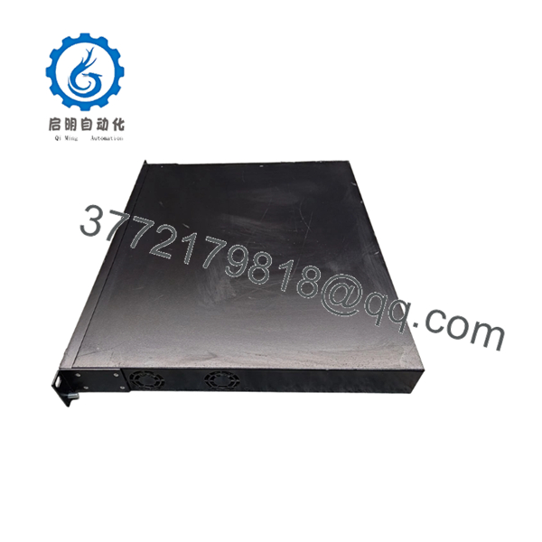
| Form Factor | 1RU rack-mountable chassis |
| Physical Dimensions | 17.4 x 14.5 x 1.7 inches (44.2 x 36.8 x 4.4 cm) |
| Shipping Weight | Approximately 15.20 lbs (6.89 kg) |
Product Introduction & Supply Chain Strategy
The Enterasys B3G124-48P is a high-performance, stackable Gigabit Ethernet switch engineered to deliver enterprise-class Layer 3 routing and secure policy enforcement at the industrial or campus network edge. Featuring 48 fixed 10/100/1000 Mbps copper ports with integrated IEEE 802.3af Power over Ethernet (PoE), this module efficiently distributes both data and electrical power to endpoints like IP cameras, wireless access nodes, and access control card readers. Its specialized hardware architecture ensures wire-speed performance and user-based access control, making it highly dependable for multi-device processing cells that require local policy sandboxing.
Because the Matrix B3 ecosystem has been discontinued by the manufacturer for several years, sourcing the B3G124-48P as a New Surplus asset is an essential strategic procurement insurance policy. Integrating low-cost refurbished or pulled substitutes introduces critical failure risks into your automation loop, including weakened internal power transformer coils, faulty PoE regulators, and memory sectors that can trigger sudden reboots. Acquiring un-deployed, factory-sealed inventory safeguards your facility’s Total Cost of Ownership by providing a pristine 10-to-15 year asset lifespan, eliminating intermittent packet drops, and protecting your lines from sudden multi-day network blackouts.
Installation & Configuration Guide
Stage 1: Pre-Installation (Prep & Safety)
- Completely isolate electrical power feeds leading to the network enclosure or open rack shelf.
- Put on a standard grounded anti-static wrist strap, securing the terminal alligator clip to a bare metal grounding point on the server rack frame.
- Access the existing switch CLI using a serial cable and execute
show configandshow systemcommands; log the output to a secure backup directory to preserve your VLAN layouts, network policies, and IP mapping. - Document the physical patch panel cabling by taking clear photographs of the 48 network connections and any active SFP uplink fiber pairs.
Stage 2: Removal
- Unplug the primary AC power line from the back panel socket. If your node utilizes an external auxiliary power unit, disconnect that interface clip fully before proceeding.
- If stacking cables are installed on the rear panels, unfasten the securing thumb screws carefully and decouple the stacking loops from the unit.
- Disconnect all 48 RJ-45 copper patch lines, taking care not to break the fragile locking tabs on the connector boots.
- Support the bottom weight of the switch, loosen the four front-facing mounting screws from the rack ears, and extract the switch assembly smoothly from the rack rails.
Stage 3: Installation (Clone & Seat)
- Carefully unpack your New Surplus B3G124-48P switch within your static-controlled workspace and inspect the structural frame and the 48 copper interfaces for shipping damage.
- Align the switch with the open 1RU slot, slide it straight back along the shelf guides, and fasten the front mounting brackets securely to the rack rails.
- Reconnect the rear stacking cables if this unit is joining an active hardware stack, tightening the thumb connectors securely.
- Insert all 48 network patch lines and optical SFP transceivers into their corresponding original port coordinates.
Stage 4: Power-On & Testing
- Re-seat the primary AC power line cord into the rear plug socket.
- Watch the front diagnostic LED array; the initialization cycle must complete successfully, and the system light must stabilize into a clean green state without throwing localized system faults.
- Connect your engineering station to the RJ-45 serial console interface using parameters set to 9600 baud, 8 data bits, no parity, and 1 stop bit.
- Log into the local Enterasys prompt, transfer your archived backup configuration script back to the flash directory via TFTP, and execute a configuration write commit to secure your settings.

- B3G124-48P
- B3G124-48P
Firmware/Software Versions & Upgrade Notes
The Matrix B3 series switch relies on dedicated firmware images engineered to align with Enterasys policy-driven network management systems. To maintain synchronization across active stack nodes, all connected boards must run the exact same operational image binary.
⚠️ CRITICAL FIRMWARE INTEGRATION WARNING: When adding this New Surplus switch to an existing stack assembly, check the firmware version pre-loaded on the new board before connecting the rear stack loop cables. Connecting a node running an older major code string (such as 4.x or 5.x) to a running stack that uses version 6.x can cause severe backplane handshake collisions, stall the master controller election, or drop the entire stack management interface offline. Always match and update standalone images via serial CLI prior to final physical hardware integration.
Frequently Asked Questions (FAQ)
Why should I prioritize a New Surplus Enterasys switch over a refurbished alternative?
A New Surplus B3G124-48P switch guarantees that the unit contains pristine internal traces, un-degraded internal power transformers, and completely fresh RJ-45 port springs. Refurbished alternatives are typically salvaged from decommissioned enterprise environments where they have logged thousands of thermal cycles under full load, leaving them highly susceptible to sudden logic component wear, interface dropping, and localized PoE circuit failure.
Does this switch support standard modern PoE+ devices requiring 30 Watts of power?
No. The legacy B3G124-48P platform is built to the original IEEE 802.3af PoE standard, which delivers a maximum of 15.4 Watts of power per port. If your facility requires deployment of high-power modern pan-tilt-zoom IP cameras, building access monitors, or dual-radio wireless access points that strictly demand the IEEE 802.3at PoE+ standard (30 Watts), this legacy platform will not supply sufficient power and you will require external midspan injectors or a newer G2 hardware series.
Can I hot-swap this switch while it is a member of an active, operating stack?
While the logical architecture allows a stack to maintain operations if a member drops offline, you must never hot-swap or hot-plug the rear proprietary stacking cables while the unit is actively powered on. Jolting the stacking backplane buses while they are conducting active signaling can trigger severe logic loops, drop neighboring stack interfaces, or cause localized damage to the internal stacking port circuits. Always isolate power before modifying stacking chains.
What is the role of the 4 SFP ports, and can they run concurrently with the last 4 copper ports?
The 4 SFP ports are configuration combo interfaces that are mechanically paired with the final 4 copper ports (ports 45 through 48). When you insert an optical SFP transceiver into one of these expansion slots to run a long-distance fiber uplink, the corresponding copper RJ-45 interface directly beside it is automatically disabled by the internal logic path. You cannot utilize the copper port and its paired SFP slot simultaneously.
What should I do if the switch configuration is password-protected from the factory check?
Every New Surplus unit undergoes factory quality control testing and is cleared back to original factory defaults before final packaging. In the unlikely event that you encounter a localized credential prompt, connect via the serial console interface, cycle the power, press the escape key during the initial BootROM initialization phase, and execute the standard clear password string to reset the internal authentication tables safely.
What warranty terms back this legacy Enterasys network asset?
We include a comprehensive 1 year operational warranty covering all integrated component groups, port matrices, and power modules. If the hardware experiences any internal electrical faults or unexpected component failures during standard service inside this protection window, our team will provide an expedited replacement unit to minimize downtime risks across your facility.



