WhatsApp: +86 16626708626
 Email:
 Phone: +86 16626708626
Description
Key Technical Specifications
The following specifications are documented for the MMS 3125 family. The precise /022-020 configuration must be verified against its nameplate and ordering code.
| Parameter | Specification |
|---|---|
| Manufacturer | EPRO / Emerson |
| Model | MMS3125/022-020 |
| Product family | MMS 3000 |
| Product type | Dual-channel bearing vibration transmitter |
| Measurement type | Absolute vibration |
| Sensor inputs | Two independent channels |
| Sensor compatibility | PR 9264 series and compatible IPC piezoelectric sensors |
| Dynamic input signal | 4 Vpp or 8 Vpp, depending on hardware configuration |
| Frequency response | High-pass filter: 5–6,000 Hz; low-pass filter: 50–12,000 Hz |
| Nominal supply voltage | +24 V DC |
| Permissible supply voltage | +18 to +31.2 V DC |
| Power consumption | Maximum 6 W, depending on installed options |
| Analog outputs | Configurable 0/4–20 mA current outputs, depending on configuration |
| Maximum analog output load | 500 Ω |
| Standard configuration interface | RS-232 |
| Optional communication | RS-485 with EPRO protocol V2.0 or PROFIBUS DP |
| Function outputs | Up to five, depending on hardware configuration |
| Enclosure | Aluminum |
| Protection rating | IP65 |
| Operating temperature | −20 to +65°C, subject to mounting and thermal restrictions |
| Relative humidity | 0–95%, non-condensing |
| Maximum net weight | 1.3 kg, depending on hardware options |
| Configuration software | MMS 3910W |
Source: EPRO MMS 3125 technical datasheet, document 6000-00050, version 1.01.
Product Introduction
The EPRO MMS3125/022-020 is a field-mounted, dual-channel bearing vibration transmitter designed to convert sensor signals into electrical measurements for machinery condition monitoring. It supports absolute vibration measurement using compatible piezoelectric or capacitive sensors, with configurable measurement characteristics and frequency filtering.
The transmitter provides two measurement channels, analog current outputs, and configurable limit and channel-status outputs, depending on the installed hardware options. It is suitable for vibration monitoring on compressors, pumps, fans, gearboxes, and turbine equipment. Configuration uses the MMS 3910W software package, which must be obtained separately.
Installation & Configuration Guide
Planning estimate: 30–60 minutes for a straightforward replacement. Allow additional time for sensor verification, configuration recovery, and alarm testing.
Stage 1: Pre-Installation Preparation
- Confirm the complete model number. Verify MMS3125/022-020 and check the nameplate, hardware options, and connector arrangement.
- Review the approved maintenance procedure. Notify operations and establish the required machinery monitoring and protection state.
- Apply electrical safety controls. Isolate the power supply where required and follow site lockout/tagout procedures. Do not assume the transmitter supports hot replacement.
- Prepare tools. Use an ESD wrist strap where appropriate, a suitable screwdriver, a multimeter, wire labels, and a camera.
- Document the existing configuration. Record sensor types, channel assignments, measurement units, filter settings, alarm thresholds, analog output scaling, and communication parameters.
Stage 2: Remove the Existing Transmitter
- Confirm that the maintenance authorization and isolation requirements have been met.
- Photograph the existing connections and identify both sensor channels.
- Label and disconnect the power, sensor, analog output, communication, and function-output wiring as applicable.
- Release the mounting hardware and remove the transmitter without stressing the cable glands or sensor connectors.
- Inspect the mounting surface, connector contacts, cable insulation, and enclosure for damage or contamination.
- Retain the old unit until the replacement passes all required functional tests.
Stage 3: Install the Replacement
- Verify hardware compatibility. Confirm the sensor input configuration, communication option, current-output arrangement, and function-output type.
- Mount the transmitter in the approved position. The OEM documentation recommends orienting cable glands downward where practicable.
- Reconnect both sensor channels according to the applicable wiring diagram. Do not mix sensor types unless the specific hardware configuration permits it.
- Reconnect power, analog outputs, communication wiring, and function outputs as installed.
- Verify supply polarity, grounding, shielding, and terminal assignments before energizing.
- Check that cable glands and enclosure seals maintain the required environmental protection.
Stage 4: Configuration and Functional Testing
- Restore power in accordance with the site procedure.
- Check the transmitter’s status and sensor supervision indications.
- Connect the MMS 3910W configuration software using the supported interface.
- Verify the sensor sensitivity, measurement mode, frequency filters, scaling, output calibration, and alarm thresholds.
- Confirm the configured 0/4–20 mA output response against a suitable test signal and the receiving PLC or DCS input.
- Test configured limit outputs and channel-status indications using an approved test procedure.
- Confirm that sensor faults and module faults produce the expected diagnostic indications.
- Record the test results, restore the approved protection configuration, and obtain operations authorization before returning the equipment to service.
Important commissioning cautions
- The
/022-020suffix should not be used to infer every installed option without the OEM ordering documentation. - Analog output scaling must match the receiving control-system input configuration.
- A transmitter configured for a different sensor sensitivity or measurement characteristic can produce incorrect vibration values even when the current output appears normal.
- The MMS 3910W configuration software is not included automatically with every transmitter.
- Installation and commissioning should be performed by personnel trained in the equipment and the site’s machinery protection procedures.
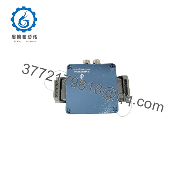
MMS3125/022-020
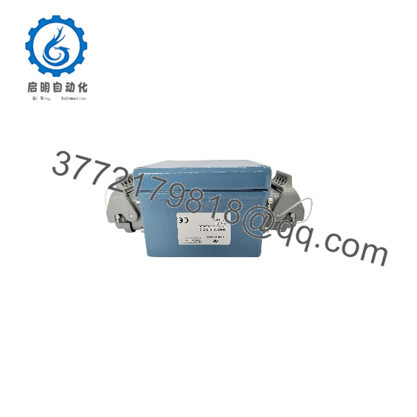
MMS3125/022-020
Frequently Asked Questions
Q1. What does the EPRO MMS3125/022-020 do?
It measures absolute bearing vibration through two sensor channels and converts the selected vibration characteristic into electrical outputs for monitoring and protection systems. The available measurement modes include vibration acceleration, velocity, and displacement-related amplitude characteristics, depending on configuration.
Q2. Which sensors can be connected to the MMS3125?
The MMS 3125 documentation identifies PR 9264-series absolute vibration transducers and compatible IPC piezoelectric sensors. The two input channels are specified for identical input configurations, so verify the exact sensor type and sensitivity before installation.
Q3. Does the MMS3125/022-020 support PROFIBUS DP?
The MMS 3125 family offers PROFIBUS DP as an optional communication interface. However, the available family datasheet does not conclusively establish that this specific /022-020 unit includes that option. Confirm the ordering code or inspect the unit’s hardware before designing the communication connection.
Q4. Can I replace the transmitter without changing the configuration?
Not necessarily. Sensor sensitivity, measurement mode, filter settings, output scaling, alarm thresholds, and function-output assignments may need to be restored. Record the original settings before removal and verify the replacement against the approved plant configuration.
Q5. Is the MMS3125/022-020 still available as new original stock?
The model appears in industrial spare-parts listings, but listings alone do not establish current OEM production status or the condition of a particular unit. Ask the supplier to confirm physical inventory, serial-number details, actual product photographs, and whether the unit is new original, new surplus, or refurbished and tested.
Q6. Why does the analog output read 0 mA?
The MMS 3125 documentation states that a detected module or sensor fault changes the status of the OK output and causes the 4–20 mA current output to indicate 0 mA. Check sensor wiring, input signal validity, supply voltage, and diagnostic outputs before concluding that the transmitter has failed.
Q7. What should I confirm before purchasing a replacement?
Confirm the following with the supplier:
- Exact model: MMS3125/022-020.
- Sensor input configuration and supported sensor sensitivity.
- Analog output type and scaling.
- Communication interface and function-output hardware.
- Physical stock status and declared product condition.
- Warranty duration, dispatch lead time, and return terms.
- Availability of configuration records or functional test documentation.
Procurement recommendation: Treat the complete /022-020 designation as essential. A transmitter from the same MMS 3125 family may have different communication, sensor-input, or output options and may not be a direct replacement.