
 WhatsApp: +86 16626708626
 Email:
  Phone: +86 16626708626
Description
3. Key Technical Specifications
| Parameter | Value |
|---|---|
| Model | C5G124-24P2-G |
| Manufacturer | Extreme Networks |
| Product Family | C-Series C5 |
| Product Type | Managed Gigabit PoE+ Switch |
| Access Ports | 24 × 10/100/1000BASE-T PoE+ RJ45 |
| Uplink Ports | 4 × Combo Gigabit SFP |
| Stacking | 2 × Dedicated High-Speed Stacking Ports |
| Switching Capacity | 48 Gbps per switch |
| Forwarding Rate | 35.7 Mpps |
| Stack Bandwidth | 128 Gbps |
| Aggregate Throughput | 176 Gbps |
| PoE Standard | IEEE 802.3af / IEEE 802.3at (PoE+) |
| Layer Features | Layer 2 and Layer 3 Switching |
| Network Protocols | VLAN, STP/RSTP/MSTP, LACP, QoS, IPv4 Routing |
| External Power | RPS (Redundant Power Supply) Connector |
| Management | CLI, SNMP, WebView, SSH, Telnet |
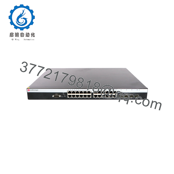
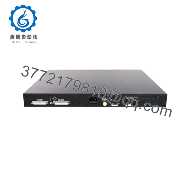
The C5G124-24P2-G is the TAA-compliant version of the C5G124-24P2, featuring 24 PoE+ Gigabit ports, 4 combo SFP uplinks, 2 dedicated stacking ports, and an external redundant power supply connector.
4. Product Introduction
The Extreme Networks C5G124-24P2-G is a stackable enterprise Ethernet switch designed for organizations requiring Gigabit connectivity with integrated Power over Ethernet. It supports Layer 2 switching and Layer 3 routing, making it suitable for campus access, branch offices, surveillance networks, VoIP deployments, and wireless access point aggregation.
Its dedicated stacking architecture allows multiple switches to operate as a single logical unit, simplifying management while increasing bandwidth and resiliency. The combination of PoE+, Gigabit uplinks, and enterprise routing capabilities makes it a practical choice for maintaining existing C-Series installations where long-term hardware compatibility is required.

- C5G124-24P2-G
- C5G124-24P2-G
5. Installation & Configuration Guide
Stage 1 – Pre-Installation Preparation (10 Minutes)
⚠️ Safety First
- Notify network users of the maintenance window.
- Save both the running and startup configurations.
- Verify all connected PoE devices can tolerate the outage.
- Disconnect AC power before servicing.
- Wait at least five minutes before opening or replacing hardware.
Tools Required
- Grounded ESD wrist strap
- Phillips screwdriver
- Digital multimeter
- Console cable
- Cable labels
- Smartphone for documenting port assignments
Data Backup
- Export the switch configuration.
- Record the firmware version.
- Photograph the rear and front panel connections.
- Label every Ethernet and fiber connection.
Stage 2 – Removing the Existing Switch (10 Minutes)
- Disconnect uplinks.
- Disconnect PoE-powered devices.
- Remove console and management cables.
- Disconnect power.
- Remove rack mounting screws.
- Carefully remove the switch from the rack.
⚠️ Keep the original unit available until the replacement has successfully completed operational testing.
Stage 3 – Installing the Replacement (10 Minutes)
- Wear an ESD wrist strap.
- Verify the replacement model is C5G124-24P2-G.
- Mount the switch securely.
- Connect the power source.
- Restore network connections using the documented labels.
- Connect the console cable.
- If stacking is used, reconnect both dedicated stacking cables.
Installation Checklist
- ☑ Model verified
- ☑ Rack secured
- ☑ Power connected
- ☑ Stack cables installed
- ☑ Network cables restored
Stage 4 – Power-On & Testing (15 Minutes)
Pre-Power Checks
- Verify AC input.
- Confirm RPS connection if installed.
- Inspect cooling airflow.
- Check stack cable seating.
Startup Procedure
- Apply power.
- Observe the boot sequence.
- Verify the system LED reaches normal status.
- Connect through the console.
- Verify firmware version.
- Confirm stack membership.
- Verify PoE delivery.
- Test VLAN connectivity and Layer 3 routing.
⚠️ Troubleshooting Notes
- Stack member not detected: Verify stacking cables and stack IDs.
- PoE devices remain offline: Check the available PoE power budget and port configuration.
- Firmware mismatch: Install the same firmware revision across all stack members before joining them to the stack.
- Configuration mismatch: Synchronize software before restoring the saved configuration.
6. Frequently Asked Questions (FAQ)
Q1. What does the “-G” suffix indicate?
The C5G124-24P2-G is the TAA-compliant version of the standard C5G124-24P2, intended for deployments that require compliance with the U.S. Trade Agreements Act. Hardware functionality is otherwise equivalent.
Q2. How many stack members are supported?
The C-Series C5 supports high-speed stacking, allowing multiple switches to operate as a single logical switch with centralized management and up to 1,024 Gbps of stack bandwidth.
Q3. Does this switch support PoE+?
Yes. All 24 RJ45 ports support IEEE 802.3af and IEEE 802.3at (PoE+), making the switch suitable for powering IP phones, wireless access points, and security cameras.
Q4. Is this model still manufactured?
No. The C-Series has reached end-of-sale and end-of-support status. Current availability primarily consists of genuine New Surplus inventory and professionally tested refurbished units.
Q5. Can I add a new switch to an existing stack without reconfiguring everything?
Generally, yes. If the replacement switch runs a compatible firmware version, it can be added to an existing stack and inherit the stack configuration. Before installation, verify firmware compatibility and stack software levels to prevent synchronization issues.
Q6. What installation issues occur most often?
The most common field issues are:
- Mixing firmware revisions within the same stack.
- Connecting stack cables in the wrong order.
- Exceeding the available PoE power budget.
- Forgetting to document VLAN assignments before replacement.
One mistake I see repeatedly is replacing a failed switch with a spare running an older firmware release. The hardware powers up normally, but the stack refuses to synchronize. Before inserting the replacement, compare the firmware version, save the existing configuration, and verify the stack topology. Those simple checks usually eliminate most commissioning delays.



