
 WhatsApp: +86 16626708626
 Email:
  Phone: +86 16626708626
Description
Key Technical Specifications
| Parameter | Specification |
|---|---|
| Manufacturer | FANUC |
| Part Number | A06B-0272-B605 |
| Motor Series | Alpha iS |
| Motor Model | Alpha 40/4000 iS |
| Product Type | AC servo motor |
| Rated Output | 5.5 kW |
| Rated Speed | 3,000 rpm |
| Maximum Speed | 4,000 rpm |
| Rated Motor Voltage | 204 V AC |
| Phase | 3-phase |
| Rated Frequency | 200 Hz |
| Rated Current | Approximately 16 A |
| Shaft Type | Tapered shaft |
| Brake | 90 V DC |
| Encoder | A64 / A64iA |
| Cooling | No integral fan |
| Maximum Torque | Approximately 115 N·m |
| Rotor Inertia | Approximately 0.0009 kg·m² |
| Weight | Approximately 34.7 kg |
The 5.5 kW, 204 V, 200 Hz, 3-phase, 3,000 rpm and 4,000 rpm specifications are corroborated by multiple aftermarket technical records.
The A64 encoder, tapered shaft, 90 VDC brake, and absence of an integral fan are specifically identified in FANUC motor cross-reference listings.
Product Introduction
The FANUC A06B-0272-B605 is an Alpha iS-series AC servo motor designed for high-power servo-axis applications in FANUC CNC and robotic motion systems. The motor is identified as the Alpha 40/4000 iS, with a 5.5 kW rated output, 3,000 rpm rated speed, and 4,000 rpm maximum speed.
The B605 configuration combines a tapered shaft, 90 VDC holding brake, and A64 encoder. These details are critical when replacing a failed motor because shaft geometry, brake voltage, and encoder feedback must match the FANUC amplifier and mechanical assembly.
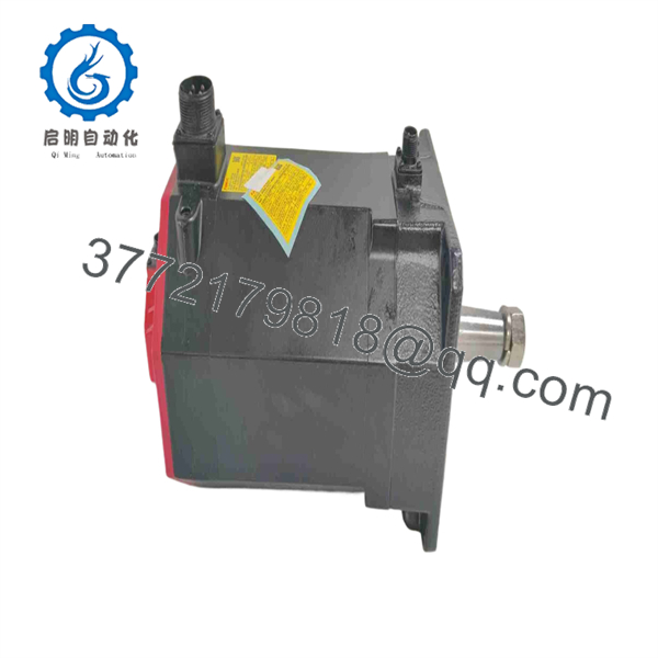
A06B-0272-B605
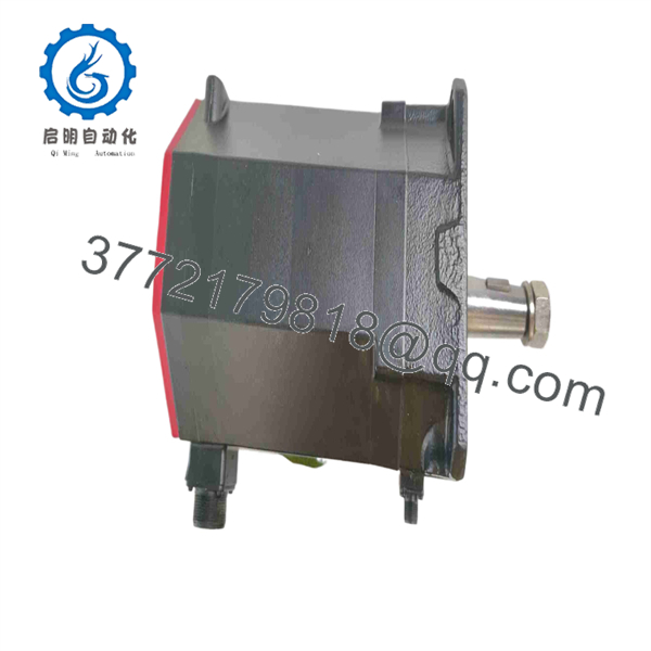
A06B-0272-B605
Installation & Configuration Guide
Stage 1 — Pre-Installation Preparation
- Verify the complete motor marking: A06B-0272-B605.
- Confirm the existing motor is an Alpha 40/4000 iS configuration.
- Record the amplifier model, motor cable connections, encoder cable, and brake wiring.
- Back up the relevant FANUC controller and servo parameters before replacing the motor.
- Apply plant LOTO procedures.
- Isolate the servo amplifier’s incoming power.
- Allow the DC bus and associated circuits to discharge for at least 5 minutes, or longer if required by the equipment service procedure.
- Confirm the replacement motor’s shaft and mounting dimensions before lifting it into position.
At approximately 35 kg, this motor should be handled with appropriate lifting equipment rather than manually positioned into the machine.
Stage 2 — Removing the Existing Motor
- Place the robot/CNC machine in the approved maintenance state.
- Isolate and verify the servo power supply.
- Label the motor power, encoder, and brake connections.
- Disconnect the motor cables without pulling on the connectors.
- Release the motor from the mechanical mounting.
- Support the motor before removing the final mounting hardware.
- Carefully withdraw the motor from the axis assembly.
- Inspect the coupling, gearbox/input shaft, mounting face, and cable connectors.
Do not rotate or force the mechanical coupling during removal. A damaged coupling or gearbox can produce symptoms that resemble a defective servo motor.
Stage 3 — Installing A06B-0272-B605
- Verify the replacement part number and motor nameplate.
- Confirm the tapered shaft matches the machine’s mechanical interface.
- Position the motor against the mounting surface without forcing the shaft into alignment.
- Secure the motor using the specified mounting hardware and torque values from the machine service documentation.
- Reconnect the motor power cable.
- Connect the A64 encoder feedback cable.
- Connect the 90 VDC brake circuit.
- Verify that cables are routed clear of moving parts and high-temperature surfaces.
- Confirm grounding and shielding arrangements before energizing the system.
The 90 VDC brake specification must not be treated as an interchangeable generic brake input. Verify the FANUC amplifier/controller output and machine wiring before applying voltage.
Stage 4 — Power-On & Testing
After installation:
- Verify motor and amplifier part-number compatibility.
- Check motor power and encoder connections.
- Verify brake operation before enabling the servo axis.
- Power the system according to the FANUC maintenance procedure.
- Check servo amplifier diagnostics.
- Confirm encoder feedback is detected correctly.
- Perform a controlled low-speed axis test.
- Check rotation direction and axis position.
- Verify servo following error and alarm status.
- Run the axis through the required travel range before returning the machine to production.
Common Replacement Mistakes
Wrong motor variant: The A06B-0272 family contains different shaft, brake, encoder, and modification configurations. Matching only the basic A06B-0272 number is insufficient.
Brake mismatch: B605 uses a 90 VDC brake. A different brake configuration should not be substituted without engineering verification.
Encoder mismatch: The B605 configuration is associated with the A64/A64iA encoder. The feedback device must be compatible with the servo amplifier and controller configuration.
Ignoring mechanical alignment: A servo motor can pass an electrical test and still cause excessive vibration, coupling wear, or positioning errors if the shaft and load are misaligned.
Confusing rated and maximum speed: The published data identifies 3,000 rpm as rated speed and 4,000 rpm as maximum speed. These values should not be treated as equivalent operating points.
Frequently Asked Questions (FAQ)
1. What is FANUC A06B-0272-B605?
It is a FANUC Alpha 40/4000 iS AC servo motor used for servo-axis motion applications. The configuration includes a tapered shaft, 90 VDC brake, and A64 encoder.
2. What is the rated output of A06B-0272-?
The motor is rated at 5.5 kW. Available technical records also identify 3,000 rpm rated speed and 4,000 rpm maximum speed.
3. What brake does the motor use?
uses a 90 VDC brake. This is an important identification feature because other FANUC motor configurations can use different brake arrangements.
4. What encodd?
The configuration is listed with an A64/A64iA encoder. Verify the actual encoder marking on the replacement motor and compare it with the existing controller configuration.
Does have an integral cooling fan?
No. FANUC motor cross-reference data identifies the configuration as No Fan.
6. Can another l?
Not automatically. The shaft type, brake voltage, encoder, seals/modifications, electrical characteristics, and mechanical interface must all be checked. For example, FANUC-related listings distinguish from versions carrying additional #S* seal modifications and other suffixes.
7. What should be verified before purchasing?
For a FANUC servo replacement, verify:
- exact part number
- Alpha 40/4000 iS motor designation
- 5.5 kW rating
- 3,000 rpm rated speed
- 4,000 rpm maximum speed
- 204 V AC / 3-phase configuration
- Tapered shaft
- 90 VDC brake
- A64/A64iA encoder
- No-fan configuration
- Machine and servo-amplifier compatibility
- Motor cable and encoder connector configuration
- New, unused, refurbished, or repaired condition
For a production machine, the safest replacement decision is based on the complete FANUC motor specification and the existing amplifier/machine configuration, not simply the physical appearance of the motor.



